W Engine Types and Components [Introduction with Complete Details]
What is W Engine?
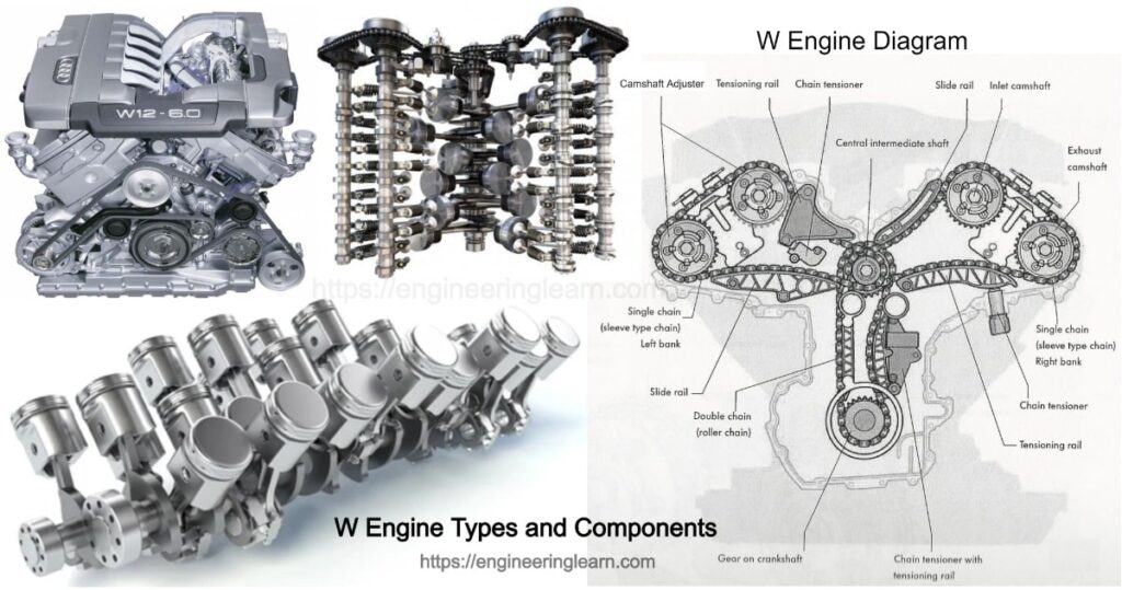
W Engine Types and Components :- The W engines refers to those engines which belong from the W family and are a combination of two VR engine which is based on the modular design principle. The W engines are formed by placing the cylinders of one bank at an angle of 15 degrees with respect to each other whereas the other two VR banks at a V-angle of 72 degrees. (Types of Engines)
What Does the W Engine Stand For?
The design of V and VR engines were combined to develop a highly efficient engine which was later known as W engine. The engine was developed with an aim of building more compactable engine which could inculcate large number of cylinders. In case of V engines, the cylinders are distributed into two banks.
There are banks of cylinders in W8 and W12 engines which are aligned at a V-angle of 72 degrees with respect to each other. Similarly in the VR engine, the cylinders within the bank develops a V-angle of 15 degrees. Once the W engine is viewed particularly from the front, the configuration of the cylinder looks like a double-V. Keeping these two V’s of the right and left cylinder banks into a combination, a W engine is formed. This is how this engine was named as W engine.
VR Engine
There is a specific requirement of a powerful alternative which is suitable for transverse mounting for use in small or mid-size vehicles which saw the development of the VR engine. The Six cylinders offset is designed at a V-angle of 15 degrees which is accommodated in a fairly slender and quite short engine block. Unlike the other designs, the engine only has one cylinder head which makes it possible to supply the golf with a compact VR6 engine.
Similar Components of VR and W Engine
There are some essential components which are from the modules of the VR engine family and are integrated into the new W engine concept with a very simple principle. This system results in a series of compact gasoline engines which ranges from W8 to W16. There are numerous components of the VR and W series which are identical as:
• Valves, valve springs and valve seat inserts.
• Roller rocker fingers.
• Valve clearance compensating elements.
In evolving the 6-cylinder engine, the VR6 engine stands out being compact. It is quite short as compared to the comparable inline engine and is also narrower than the V engine. In a combination of two VR6 engines with a cylinder angle of 72 degrees makes a W12 engine. Whereas, a W16 engine refers to as the one which is obtained by merging two cylinders to each cylinder bank of a W12 engine.
Types of W Engines
There are wide range of W engines, about which one definitely needs to know. Scroll down to know a lot about the different types of W engines:
1) W3 Engine
W3 refers to as those engines which comprises of three banks of cylinders which is also known as the broad arrow engines. It is named so because of their shape which resembles the broad arrow property mark of the British government. It is a piston engine where 3-4 engines are found using the same crankshaft.
2) W6 Engine
W16 refers to as those engines which comprises of a sixteen cylinder piston engine accompanied with four banks of four cylinders in a W configuration. These type of engines are very rarely produced, with a notable exception of the Volkswagen Group 8.0 engine which had been used since the year 2005 in the Bugatti Veyron and its related models
3) W8 Engine
W8 refers to as those engines which comprises of an eight-cylinder in a W configuration engine with the cylinders mounted on the crankcase in two different sets of four and all the eight pistons driving a common crankshaft. In common words, the W8 is basically a two parallel inline-four engine which shares a common crankshaft.
4) W12 Engine
W12 engines are referred to as those engines which comprises of three banks including four cylinders which were used a lot as the aircraft engines from the year 1917 until the 1930. It was designed which got named as an unsuccessful W12 engine and was intended to compete in 1990. Whereas these were less commonly used automobiles than V12 engines, a W12 petrol engine was produced by Volkswagen Group since 2001. This four-bank engine was used in various cars and were sold under the brands like Audi, Bentley and Volkswagen.
5) W16 Engine
The W16 refers to as those engines which comprises of two narrow-angle V8s, which are found forming a W. W16 is a single and massive engine with only one crankshaft which is called a pair of V8s and is just a handy way to help in visualising the pistons.
6) W18 Engine
W18 refers to as those engines which comprises of an eighteen cylinder piston engine which is found having a single crankshaft with three banks of six cylinders arranged in an inverted broad arrow configuration.
COMPARISION
When a 8-cylinder V engine is compared to a 8 cylinder W engine then the latter particularly stands out due to the compact design and relatively small external dimensions.
Specification of a W8 engine
• Displacement is around 244 cu in
• Bore 3.307 inches
• Stroke 3.550 inches
• Number of cylinders 8
• Number of cylinder heads 2
• Offset ± 0.492 inches
• Bank offset 0.512 inches
• The V-angle amongst cylinder heads and banks is 72 degrees
• The V-angle amongst the cylinders in a bank is kept around 15 degrees
• Number of valves 4 per cylinder
• Crankshaft journal offset 218 degrees
• Firing order 1-5-4-8-6-3-7-2
Specification of a W12 engine
• Displacement is around 366 cu inches
• Bore 3.307 inches
• Stroke 3.550 inches
• Number of cylinders 12
• Number of cylinder heads 2
• Offset ± 0.492 inches
• Bank offset 0.512 inches
• The V-angle amongst cylinder heads and banks is 72 degrees
• The V-angle amongst the cylinders in a bank is kept around 15 degrees
• Number of valves 4 per cylinder
• Crankshaft journal offset +12 degrees
• Firing order 1-12-5-8-3-10-6-7-2-11-4-9
Components of W Engine
W engines comprises of these following components:
• Cylinder block
• Crankcase lower section with bearing support
• Crankshaft with connecting rods and pistons
• Balancing shafts Engine — Mechanics
• Cylinder heads
• Oil sump and oil pump
• Crankshaft drive
• Timing chain drive
• Belt drive for auxiliary components
• Multi-part intake manifold
The crankcase lower section is a bearing support which is accompanied with the integral bearing seats. The bearing support is made of material named as aluminium alloy. It is used as an ideal structure for the lower crankshaft main bearing caps. These bearing caps are made of grey cast iron which are embedded in the bearing support when it is casted. These are found on the thrust side of the crankshaft which gives the crankshaft bearings the strength that they require. The bearing
1. Crankpin Offset
Crankpin offset refers to as those which are responsible for controlling the relative positions of the pistons in the cylinders for an evenly timed firing sequence. The configuration of a W engine is based on a 10-cylinder engine model. All the four cycle internal combustion engines complete their own cylinder firing sequence within two complete revolutions. The angular rotation to a crankshaft is of 720 degrees. This W10 engine therefore does not need any crankpin offset. With 720 degrees of crankshaft rotation in a 10-cylinder engine, the optimum V-angle between both the cylinder banks is around 72 degrees.
Considering a 10-cylinder model engine there is no need for crankpin offset to achieve an ideal position of relative piston for the equally timed firing of each and every cylinder. The W8 engine is found having a crankpin offset of around 18 degrees which helps in achieving the same kind of ideal firing sequence as that of a 10-cylinder model also a 8-cylinder W engine requires an angular rotation of 90 degrees from the crankshaft rotation between the ignition cycle of each and every cylinder through 720 degrees of the crankshaft rotation. In order to determine the optimum crankpin offset of this engine a 90 degrees of crankshaft rotation between ignition cycles is subtracted from the 72-degree V-angle of the cylinder banks.
For instance, 72 – 90 = –18. Same is with a 12-cylinder engine which requires a 60 degrees of crankshaft rotation between the ignition cycle of each cylinder through a 720 degrees of crankshaft rotation. To understand this configuration it is important to determine the optimum crankpin offset of +12 degrees, the 60 degrees of crankshaft rotation between the ignition cycles will be subtracted from the 72-degree of a V-angle of the cylinder banks.
2. Crankshaft
The crankshafts which is used inside the W engine is manufactured from the forged tempered steel. Each pair of this connecting rod runs between the two main bearings. The drive gear of the oil pump with the toothed belt pulley is pressed against the outer main bearing and is held in place by the vibration damper.
3. Balancing Shafts of W8 Engine
The W8 engine is found having two balancing shafts which compensate the forces of inertia. The two shafts are housed inside the crankcase. The upper balancing shaft is driven using the help of a crankshaft and a toothed belt. A gear at the upper balancing shaft drives the lower balancing shaft which is at the end. The balancing shafts are installed using two holes on the clutch side of the crankcase.
A groove is founded at the end of the gear wheel of the balancing shaft. The lock plate is found engaging the grooves which locates the balancing shafts axially. While installation, the balancing shafts can be aligned with regard to the TDC position of the 1st cylinder. The balancing shafts should be rotated so that the marks on the balancing shafts are set opposite to each other. The balancing shaft drive is protected with the belt drive side using a plastic housing cover. Coming to the clutch side, the openings let’s to insert the balancing shafts together with the chain drive is sealed by an aluminum cover.
4. Chain Drive of W engine
The chain drive of an engine is mounted at the flywheel end of the engine from where the engine power is transmitted through the gear on the crankshaft to the gear of the central intermediate shaft by the means of a double chain. At this point, each camshaft of the two cylinder head is driven using a single chain. There are three hydraulic chain tensioners which ensure that an optimal chain tension is maintained.
5. Engine Lubrication
The oil which is taken out from the oil pan by the oil pump, flows through to the central oil passage and then through the external oil filter. The main bearing of the crankshaft is supplied with pressurized oil using the central oil passage.
Once the central oil duct is supplied with pressurized oil by a riser, the oil flows through the central oil duct to the spray jets for piston cooling after which it goes to the cylinder heads through equipped risers with non-returnable valves. The oil which flows to the intermediate shaft moves to the engine timing gear and then to the chain tensioner.
6. Wet-Sump Principle
The engines like W8 and W12 consist of a wet-sump lubrication system. The W12 engine has a dry-sump lubrication system specifically in Audi cars, wherein the entire oil supply is retained in the oil sump. The single-stage of oil pump draws the oil out from the wet sump through the intake line and then immediately returns it to the engine after it has been cooled down and has been filtered.
In reference to the dry-sump the work of the oil sump with the wet sump is to retain the supply of the entire oil which results in a larger volume and also affects the overall height of the engine.
7. Dry-Sump Principle
The dry-sump lubrication system is a system in which the entire oil supply is retained in an external reservoir and not in the oil sump. The oil pump is of three stage design. Two stages help in drawing the oil out from the oil sump at various points and pumps it into the reservoir.
Whereas the third stage which is known as the discharge stage returns the oil from the reservoir to the engine with the help of an oil cooler or oil filter. The oil sump can also be kept small and flat due to its lower oil volume intending to result that the engine has a smaller overall height. This requires a comparatively more complex design.
8. Oil Sump
The oil sump is the one which comprises of two aluminum parts which are die casted. The oil sump of the lower section forms an oil reservoir whereas the central oil passage is located inside the upper section of the oil sump. There are special baffles which settles the oil in the oil sump. The Level of the engine oil informs the Motronic Engine Control Module of the oil level which is inserted into the lower section of the oil sump from below close to the oil drain screw after which it is bolted into place.
2 Coolant Pump With Pump Gear In Both W Engines
The pump of the coolant is placed inside the cylinder block at the face end and is mounted directly upstream on the duct of the central coolant which is driven by the ribbed V-belt. Electronically Controlled Engine Cooling uses the small cooling circuit to the large cooling circuit which is controlled by an electrically actuated Map Controlled Engine Cooling Thermostat.
In order to replace this valve, it is necessary to remove the intake manifold by heating the wax electrically or thermocouple in the Map Cooling Thermostat which is possible to control the switching point and the coolant temperature. It makes it possible for the engine to reach the required temperature in accordance with the requirement of the engine’s operations.
Supply of Air
The air that is supplied is supplied through a tapered intake pipe. This is a four-part design which is made of an aluminum alloy. The lower section of an intake manifold is bolted to the cylinder head within the two cylinder banks. The upper section of the larger intake manifold is mounted to the lower section. The upper section of the intake manifold is designed in such a way that the manifolds for different banks can be removed separately. This made it easier to gain access within the individual ignition coils and spark plugs, for instance in a W8 engine, the supply of air for both manifolds is guided.
Exhaust System
The W8 engine comprises of an exhaust manifold with a catalytic converter for each cylinder head. A total of four oxygen sensors are required in order to control the emission which are as follows:
• Heated Oxygen Sensor (HO2S) G39
• Heated Oxygen Sensor (HO2S) G108
• The Sensor of Oxygen Beyond Three-Way Catalytic Converter (TWC) G130
• The Sensor of Oxygen Beyond Three-Way Catalytic Converter (TWC) G131
• The exhaust system uses a primary silencer and a rear silencer for each bank and a common central silencer.
The W12 engine carries two exhaust manifolds for ever cylinder head. Each of these exhaust manifolds is connected to the primary catalytic converter which is located near the engine itself. The two exhaust pipes of every bank merges on the main catalytic converter. The exhaust system inculcates a primary silencer, an intermediate silencer and a rear silencer for a particular bank. Usually four primary catalytic converters and two main catalytic converters are used to achieve an effective reduction in the emissions. To monitor the combustion mixture and to optimize the pollutant emission reduction its use is made in a total of eight oxygen sensors, four each before and after the primary catalytic converters.
SERVICING THE ENGINE
Engine Sealing
Each cylinder heads is mostly sealed off from the valve covers using a rubber gasket from its contact faces in order to stop the intake manifold by an elastomer gasket, by a two-layered gasket of embossed metal, and from the crankcase by a multilayer embossed metal gasket. The gasket within the bearing support and the upper section of the oil sump is designed in a single layer and is embossed with metal gasket. The oil pan upper and lower section of the crankcase section supports are sealed by a liquid gasket.
Liquid Gaskets
The most important application of a liquid gasket sealant is the CNC-controlled which ensures a constant sealant supply. The liquid gasket between the lower timing case cover and the upper timing case cover is decided according to the various principles. In this type of case the parts are initially bolted and then the sealant gets injected inside the groove in the upper timing case cover through the zerk-type fitting. Once the enough liquid sealant has been injected all the remaining sealant is discharged from the openings on the end of the timing case cover. Whereas it has to be replaced while repairing the gasket.
Why Is It Called Super Engine?
- The Bugatti Veyron 16.4 is the fastest yet most expensive production in the world of supercar which proves a top speed of over 400 km/h.
- It also features a super W16 engine which has 16 cylinders in 4 banks of 4 cylinders.
- It reached full production in the year 2005.
- It was named after a racing driver Mr. Pierre Veyron who won the 24 hours of Le Mans in the year 1939 while racing for the original firm of Bugatti.
- Bugatti was again claimed as the land speed record for producing cars on July 4, 2010 including the Veyron Super Sport prototype.
- During the test drive of Bugatti, its test driver Pierre Henri Raphanel, the Super Sport manager runs of 265.9 and 269.8 mph which is nearly 432kph.
