Types of Engine Valves: Valve Timing Diagram & Valve Operating Mechanism [Complete Guide]
What is an Engine Valve?
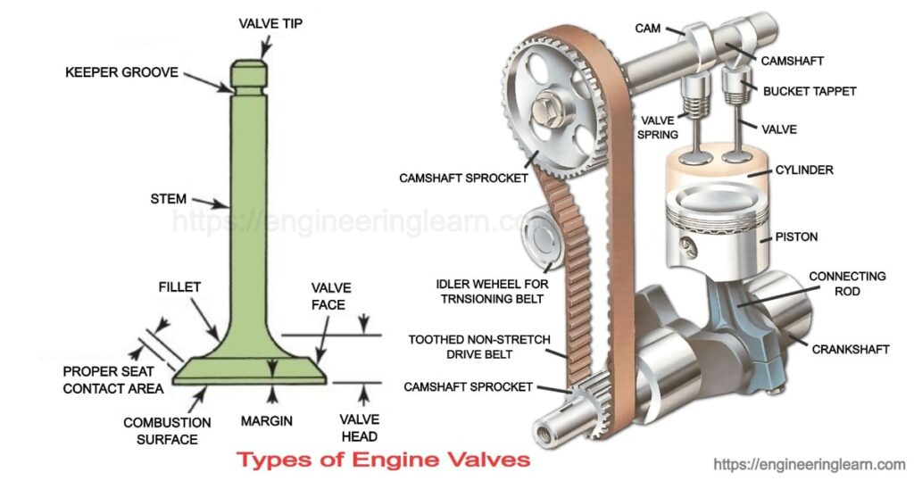
Types of Engine Valves: Valve Timing Diagram & Valve Operating Mechanism : Engine valves are mechanical components that are provided on the head of the combustion chamber of an internal combustion engine. These are provided to regulate the flow of fuel and gases in or out of the combustion chamber. Normally there are two valves provided. One of them is an inlet valve which is used to restrict and allow the flow of fuel into the combustion chamber.
Another valve is known as the exhaust valve which is used for the exit flow of exhaust gases. These valves are actuated by a cam and follower mechanism. This mechanism is run by the crankshaft with the help of a timing chain for desired opening and closing of the valve.
Inlet Valve
The Inlet valve is provided for the intake of fuel into the combustion chamber. When the inlet valve closes it seals the combustion chamber tightly and restricts more fuel to come in. As fuel coming in is at a lower temperature so inlet valve is usually made of nickel-chromium alloy steel.
Exhaust Valve
The function of the exhaust valve is to remove the burnt fuel i.e., exhaust gases out of the combustion chamber so that fresh charge can come in. As exhaust gas has a higher temperature. The exhaust valve is made of a steel alloy of silicon and chromium which has good resistance to heat.
Valve Timing Diagram
The valve timing diagram is a graphical representation of opening and closing timing and duration of valves with respect to the crank rotation. As we know the valve opens or closes at the end of the stroke but this is theoretical timing. In actual practice the timing of opening and closing is varied slightly to get the best output on the proper flow of fuel and exhaust gases. And valves are the mechanical mechanism which has some delay, so valve timing is arranged to overcome this delay. Modified valve timings improve the Volumetric efficiency of the engine.
The valve timing diagram of both petrol and diesel engine is discussed below:
The valve timing diagram of the Petrol Engine
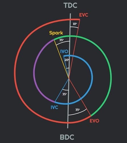
In petrol engine valve timing is as follows:
- Inlet valves open 20° prior to the intake stroke and remain open throughout the intake stroke. The intake valve closes after the 35° crank rotation after the intake stroke.
- After this before the end compression stroke 35° prior TDC spark is generated to give the proper time to ignite the fuel properly.
- During power stroke 35° prior BDC exhaust valve opens and remains open throughout the exhaust stroke. The exhaust valve closes 10° after TDC.
- As mentioned above inlet valve opens 20° prior and exhaust valve closes 10° after intake valve, during this time both valves remains open, this is known as valve overlap.
The valve timing diagram of Diesel Engine
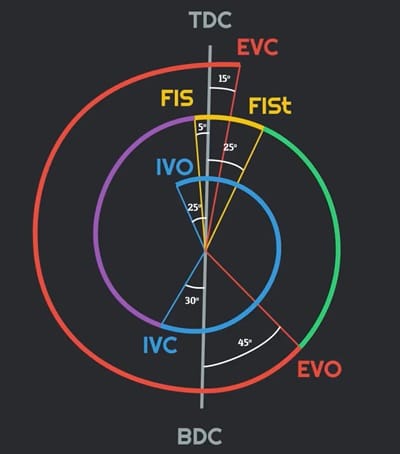
In diesel engine valve timing is as follows:
- In advance of the intake valve, 25° prior, TDC intake valve opens and remains open throughout the intake stroke. This intake valve closes after 30° BDC of the intake stroke.
- Before the end of compression stroke which is 5° prior TDC fuel injection starts and stops after 25° of TDC.
- During power stroke 45° prior BDC exhaust valve opens and remains open throughout the exhaust stroke. This exhaust valve closes after 10° TDC of suction stroke.
- As the Inlet valve opens 25° suction stroke and the exhaust valve closes 10° after suction stroke, this timing is known as valve overlap.
Types of Engine Valves
There are mainly 4 types of engine valves which are following:
- Poppet valve
- Sleeve valve
- Rotary valve
- Reed valve
1. Poppet Valve: ( Types of Engine Valves )
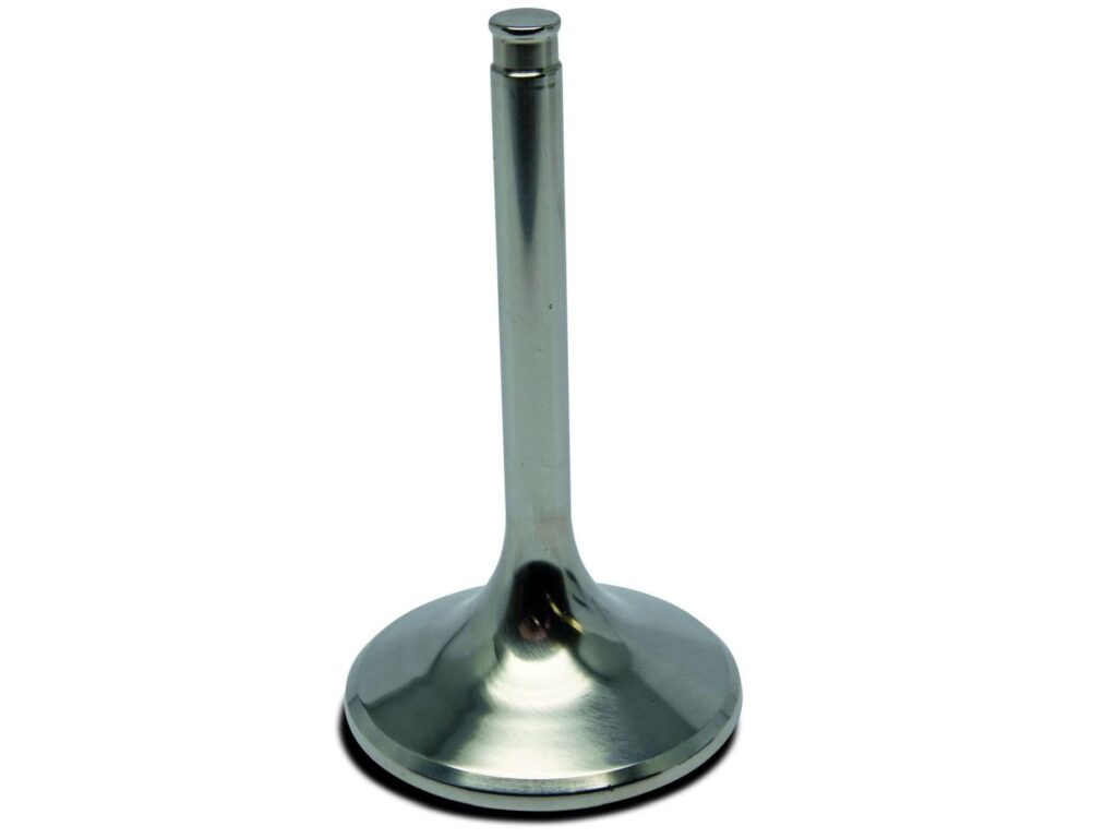
It is the most commonly used valve in automobile engines. The name of this valve is given because of its popping up and down motion. This looks similar to mushrooms hence it is also known as a mushroom valve.
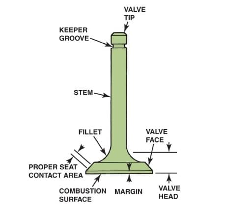
Poppet valve consists of mainly two parts one is head and other is the stem. The face of the valve is inclined 30°-40° because it has to fit properly with the valve seat. The other part is the stem. It is a long rod that has a spring retainer lock groove and its one end is in contact with the cam which is run by the crankshaft. The spring helps to seal the valve properly.
The intake valve is placed on the combustion chamber side, such that during exhaust stroke exhaust pressure helps to seal the inlet valve. The exhaust valve is placed on manifold side such that suction pressure helps to seal the exhaust valve during suction stroke.
2. Sleeve Valve: ( Types of Engine Valves )
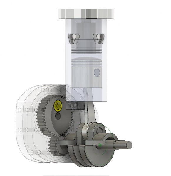
As the name suggests, the sleeve valve is a sleeve up and down type mechanism. In this valve, a tube or sleeve is provided between the piston and the cylinder wall. The cylinder wall is provided by permanent inlet and outlet ports and the sleeve is also provided with a hole for the same. This sleeve is moved up and down with a cam mechanism. When ports of sleeve come in the alignment of inlet and outlet port of cylinder wall the passage opens whereas otherwise, it is closed.
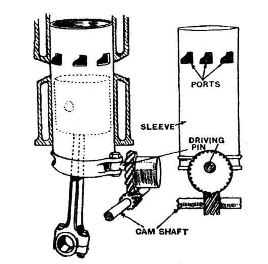
The sleeve forms an inner cylinder in which the piston reciprocates. The movement of the sleeve help to drive out the exhaust gases. The advantage of this valve is that it has a simple construction. It is noise free because there are no moving parts like rocker arm, tappet, etc. It reduce detonation & helps in effective cooling.
3. Rotary Valve: ( Types of Engine Valves )
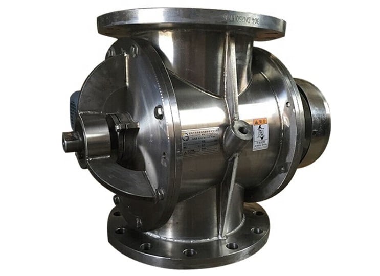
The rotary valve has an electric motor-like construction. It has an outer cylinder casing which has ports in the casing for the inlet and exhaust. Inside the cylinder, a shaft with blades is provided like the armature of the motor.
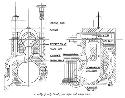
When blades come in the alignment of ports the ports closes whereas otherwise, they are open. The location of ports and the speed of blades are adjusted in such a way that it matches the valve timings.
4. Reed Valve: ( Types of Engine Valves )
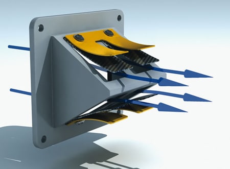
It is a mechanical strip valve. In this valve, a mechanical strip is hinged at one end. It covers the passages and allows air or charge to flow in one direction only. This valve is placed in such a way that suction pressure opens the inlet valve and closes the exhaust valve and exhaust pressure closes the inlet valve and opens the exhaust valve. It is generally used in two-stroke engines.
Types of Valve Operating Mechanism
- Side valve mechanism
- Overhead mechanism
1. Side Valve Mechanism
In this mechanism as shown in the figure, the inlet valve is placed on the side of the cylinder valve. When the camshaft rotates the cam, the lobe opens the valve directly through the tappet against the spring’s tension. When the cam lobe attains the maximum height, the valve opens completely. Additional rotation of the cam triggers the tappet to move downwards and the valve is stopped by the tension of the valve spring.
2. Overhead Valve Mechanism
As the name says in this mechanism valves are placed overhead on the combustion chamber. As the camshaft turns, the cam lobe brings the tappet upward. When the tappet moves up, it pushes the push-rod and one end of the rocker arm upwards. The other end of the rocker arm’s tip moves downward and the inlet valve opens against the spring’s tension. When the cam lobe reaches the maximum height, the valve opens fully. Further rotation of camshaft causes the tappet to move down and the valve is closed by the tension of the spring.
Image Source :- howacarworks, homemodelenginemachinist,
