Shafts: Definition, Types, Application, Materials, Size, Used, Design, Advantages & Disadvantages

What is Shafts?
Types of Shafts: Definition, Application, Materials, Size, Uses, Design, Advantages & Disadvantages :- Shaft is basically the rotating component of any machine, which is round in the cross section and is used for passing the power from one part to another or from the power producing machine to the power absorbing machine. For the transmission of power, one end of the shaft are connected with power source and the other end of the shaft are connected with the machine. Shaft can be solid or hollow according to the requirement, hollow shaft helps in reducing weight and provide advantage.
General Description of a Shaft
Shafts are one of the very important elements used in machines. They are provided for supporting the rotating part such as pulleys and gears and they are supported by bearings which rest in the rigid machine housing. The gears and pulley which is placed on shaft help in transmitting the motion. Many other rotating elements are mounted on the shaft by the help of key. They are subjected to bending moment and torque due to the reactions on the members which is supported by the shaft and torque due to the power transmission. Shafts have always circular cross sections and can be either hollow or solid.
Shafts can be classified as cranked, straight, articulated or flexible but the straight shafts are commonly used for transmitting the power.
Shafts are generally designed as steeped cylindrical bars therefore they have different diameters throughout the length, although the shafts having constant diameter are easy to produce. The magnitude of the stress in stepped shafts varies with their length. The shafts having uniform diameter are not compatible with disassembly, assembly, maintenance and these shaft produce complications while fastening the parts which is fitted to them specially bearings.
Types of Shafts
Various types of shafts are: ( Types of Shaft Keys )
1. Transmission Shaft
These shafts are stepped shafts which are used for transmitting power between one source to the other machine absorbing power. On stepped portion of shaft gear, hub or pulley are mounted for transferring motion. Example: Overhead shafts, line shafts, counter shafts and all factory shafts.
2. Axle Shaft
These shafts supports rotating element such as wheel and can fit in the housing with bearing but the axle is a non rotating element. These are mostly used in vehicles. Example: Axle in automobiles.
3. Spindle Shaft
These are the rotating part of machine; it holds the tool or workspace. They are short shaft which is used in machines. Example: Spindle in lathe machine.
4. Machine Shaft
These shafts are inside part of the assembly and they are integral part of machine. Example: Crankshaft in car engine is a machine shaft.
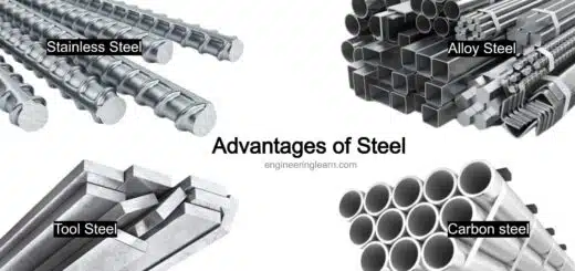
Materials Used for Shaft
Generally mild steel is the material which is used for shafts. If high strength is required then alloy steel like nickel chromium, nickel, chromium vanadium steel is used. They are usually formed by hot rolling and cold drawing and grinding.
The material which is usually used for regular shafts are carbon steel of grade 50 C12, 50 C4, 45 C8, 40 C8.
The materials which are used for shaft should have following properties:
- Material should possess high strength.
- Material should have high wear resistance.
- Material should possess heat treatment properties.
- Material should possess good mechanization.
- Material must have low notch sensitivity factor.
Standard Sizes of Shafts
- Machine shaft
Up to 25 mm with 0.5 mm steps.
- Transmission shaft
Standard size of shaft – Step sizes
25 mm to 60 mm – 5 mm step
60 mm to 100 mm – 10 mm step
110 mm to 140 mm – 15 mm step
140 mm to 500 mm – 20 mm step
Machines shaft’s standard sizes are up to 25 mm with 5 mm step. For shafts, the standard lengths are 5m, 6m and 7m but generally taken as 1m to 2m.
Stresses in Shaft
Stresses which are induced in shaft are:
- Shear stress which is induced because of the transmission of torque (torque induced due to the torsional load).
- Bending stresses which is compressive or tensile in nature induced due to the forces which is acting on the machine element such as pulleys and gear and from the self weight of shaft.
- Combined stress due to bending and torsional loads.
Design Stresses
Maximum permissible shear stresses are:
- 56000 KN/m2 for the shafts with allowance provided for keyways.
- 42000 KN/m2 for the shafts without allowance provided for keyways.
Maximum permissible bending stresses are:
- 112000 KN/m2 for the shafts with allowance provided for keyways.
- 84000 KN/m2 for the shafts without allowance provided for keyways.
Manufacturing of Shafts
Shafts are manufactured by hot rolling process. The strength of shaft is higher in case of cold rolling in comparison with hot rolling but cold rolling results in high residual stress which leads to the deformation of shaft when machined. Forging process is used for the manufacturing of larger diameter shafts. After the rolling, the shafts are then subjected for end working process where shaft’s one end are loaded on check and shaft’s other end are supported with lathe machine’s turret. For finishing the shaft, tool holds the tool post and when the power is ON chuck start rotating the shaft.
Dial gauge are used for checking the concentricity of shaft before machining it and many operations such as turning, facing, grooving, taper turning etc are performed according to the use.
Applications like high volume, CNC are best suited for end working process. And it can also executed with CNC double end machine in which shaft holds between the tool rotates and the fixtures for machining. For achieving concentricity and roundness, the rotating tools should be facing each other in centerline. Transmission shafts and motors are usually made by this process.
Power Transmission by Shaft
We know that shafts are used for power transmission therefore the formula used for calculating the power transmission is:
P = 2πNT/ 60 watt
Where, P is the power transmitted
N is the speed in revolution per minute (RPM)
T is the torque in Nm.
Speed of Shaft Used for Various Applications
Applications – Speed in RPM
- Machinery – 100 – 200
- Wood machinery – 250 – 700
- Textile industry – 300 – 800
- Light machine shop – 150 – 300
- Countershaft – 200 – 600
Shaft Design
Shaft can be design by two different processes which is based on different loading considerations:
1. Design of Shaft on the Basis of Strength
Transmission shafts are usually liable to bending moment, torsional moment, axial tensile force and their combinations. Generally shafts are subjected to combined loading of torsional stresses and bending stresses.
- Shaft subjected to tensile stress
Tensile stress = P/ A
Where, A = (π/ 4) x D²
D is Diameter of the shaft in mm
- Shaft subjected to the bending moment
Bending stress = (Mb x Y)/ I
Where,
Mb = Bending Moment
Y = D/ 2 in which D is diameter
I = Moment of inertia = (π x D⁴)/ 64
- Shaft subjected to the torsional moment
Torsional stress = Mt x R/ J
Where,
Mt = torsional moment
R = D/ 2 in which D is the diameter
J = Polar moment of inertia = (π x D⁴)/ 32
2. Design of Shaft on the Basis of Rigidity Basis
Transmission shaft are known as rigid on torsional rigidity basis if the shaft does not twist too much.
{Mt/ J} = {(G x ө)/ L}
Where,
Mt = Torsional moment in N – mm
J = Polar moment of inertia = (π x D⁴)/ 32
D = Diameter of shaft in mm
Ө = Angle of twist
G = Modulus of rigidity in N/ mm²
Advantages of Shafts
- They are less likely to jam.
- They need less maintenance in comparison to chain system.
- They have high torsional strength.
- They have high value of polar moment of inertia.
- They are very strong and less likely to be failure.
- Internal shape of a hollow shaft is hollow therefore they require less material.
- Hollow shaft have low weight in comparison with solid shaft for same value of torque transmission.
- They have high radius of gyration.
Disadvantages of Shafts
- Due to loose coupling they have power loss.
- They vibrated while rotation.
- They generate a constant noise.
- Manufacturing and maintenance costs are high.
- Difficult in manufacturing.
- Changing the speed of shaft is not easy.
- Due to mechanical problems the downtime is longer.
- Oil dripping from overhead shafting.
- Use of flexible couplings like leaf spring coupling can result in loss of velocity between the shafts.
- If failure takes place in shafts then it takes huge time in repairing.
Image Source :- rw-couplings