Types of Combustion Chamber: Functions, Advantages & Disadvantages [Complete Details]

What is Combustion Chamber?
Types of Combustion Chamber: Functions, Advantages & Disadvantages :- A combustion chamber is a confined space inside the internal combustion engine in which combustion of mixture of air and fuel takes place. When combustion of mixture takes place, the temperature and volume of mixture increases and high amount of heat energy is liberated. Due to this high pressure is created inside the combustion chamber which moves the piston up and down.
Hence, the combustion chamber is a very important part of an internal combustion engine. So, the design of combustion chamber is very important task because it affects the overall performance and other parameters of internal combustion engine.
Functions of Combustion Chamber
- It provides a confined space for the combustion of air and fuel mixture
- It houses the inlet & outlet valve for incoming and outgoing of mixture
- It houses and guides the piston
- It helps in proper combustion by proper geometry
- It withstands against the high temperature of combustion
- It prevents to spill out the exhaust of combustion
Different Types of Combustion Chamber
Combustion chambers are classified on the basis of fuel or cycle used for the combustion
- Combustion chambers in S.I. (spark ignition) engine
- Combustion chambers in C.I. (compression ignition) engine
1. Combustion Chamber in S.I. Engine
Requirements of combustion chamber in S.I. engine
• To achieve high power output
• To achieve high thermal efficiency
• Smooth running of engine
• To avoid knocking or detonation
• Long life of engine
• Minimum maintenance of engine
Factor to be considered in the design of a good combustion chamber in S.I. engine
To achieve the design of a good combustion chamber, the following factors should be considered
1. High Volumetric Efficiency
Volumetric efficiency is the ratio of actual volume sucked by the engine to the swept volume of the cylinder. For achieving higher volumetric efficiency, the largest possible inlet valve areas should be designed.
2. Avoid Hot Spot
Hotspots are the certain points inside the combustion chamber which have comparatively higher temperature. Due to these hotspots auto-ignition of fuel takes place which should be avoided to prevent knocking. Hotspot may be created by any carbon deposits, exhaust valve, spark plug etc. Sufficient cooling should be provided to avoid the hotspot and exhaust valve should be located in such a way that it receives minimum heat.
3. Location of Spark Plug and Bore Size
As the flame travelling distance increase, possibility of knocking increases. To reduce this distance spark plug should be located at the Centre. Also bore of the cylinder should be small.
4. Turbulence
Turbulence is the non-laminar flow of fuel at high speed. Turbulence is a very important factor for better combustion in SI engine. Proper turbulence can be created by
• Proper location of inlet valve
• Proper design of inlet passage
• Proper design of piston head and cylinder head
5. Surface to Volume Ratio
It is the ratio of internal surface area to the volume of combustion chamber. For better thermal efficiency and minimum heat transfer, surface to volume ratio should be minimum. To achieve this, hemispherical shape is preferred for combustion chamber.
6. Scavenging
Scavenging is the process of removing the exhaust gases by using the fresh charge. Scavenging of exhaust gas should be better. It reduces volumetric efficiency of the engine and consequently power output is reduced.
7. Wall Thickness
Thickness of wall should be uniform for uniform expansion. Here uniform expansion means due to higher temperature inside the cylinder, the walls of cylinder start to expand. So, if the thickness is uneven then expansion is also uneven which causes seizure of piston.
8. Compression Ratio
Compression ratio is the ratio of clearance volume to the total volume of the cylinder. Design of combustion chamber should be such that engine should run with highest compression ratio without knocking to achieve maximum thermal efficiency.
Types of Combustion Chamber in SI Engine
Over the years combustion chambers went through some modifications like changes in the position of the spark plug, location of inlet & exhaust valves etc. Based on these modifications’ combustion chambers can be divided into following types
- T-head type
- L-head type
- I-head type
- F-head type
1. T-Head Type: ( Types of Combustion Chamber )

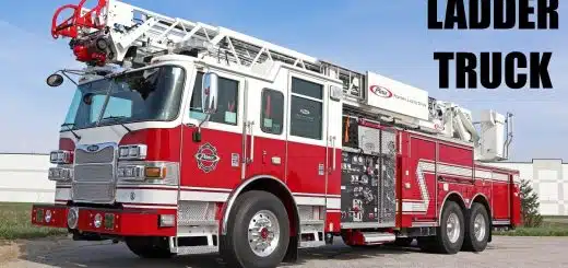
It is the earliest used type of combustion chamber. This was introduced by Ford in 1908. In this type, the inlet and exhaust valves are placed on the either side of the cylinder block. As the valves are placed on either side, they require individual camshafts to operate them. This makes it difficult to manufacture and the chance of knocking is high. Hence these types of engines became obsolete after World War 1 but they continue to be used in fire trucks until the 1950s.
2. L-Head Type: ( Types of Combustion Chamber )

This type of combustion chamber was developed to overcome the disadvantage of T-head type combustion chambers. This type was used by Ford between 1910 and 1930s. In this type, the inlet & exhaust valves are placed on the same cylinder and thus they can be operated by single camshaft. The advantage of this system is that it has a simple valve mechanism which can be lubricated easily.
This results in easy maintenance. But because of the location of the valves the distance that air has to travel is more which results in loss in velocity, eventually ending up in knocking. To avoid this, Riccardo modified the design by placing the spark plug over the valves. This reduces the distance that has to be travelled by the flame and thus the chances of knocking are less.
3. I-Head Type: ( Types of Combustion Chamber )

In this type both the valves are mounted on the cylinder head. Hence this is also known as overhead combustion chamber. The valves at the top provide direct passage for the fuel which makes it more efficient. This was first developed by Buick and it has been in use since the 1950s. Overhead combustion can also be classified into the following types-
- Bath Tub Type: In the bath tub type, spark plug is placed at the side and the valves are placed vertically at the top.

- The Wedge Type: In the wedge type the valves are placed inclined, whereas the spark plug will be at the top.

The advantages of this type of combustion chamber are-
• Less knocking
• Low emissions
• High volumetric efficiency
4. F-Head Type: ( Types of Combustion Chamber )

This type is the intermediate between the L and I type head combustion chambers. It has an inlet valve at the cylinder head similar to the I-head type and exhaust valve on the cylinder block similar to the L-head type. The F-head chamber was successfully used by Rover Company and in Willy’s jeeps.
The advantages of this type
• High volumetric efficiency
• High thermal efficiency
Individual camshafts are used for their operation which is a disadvantage.
2. Combustion Chamber in C.I. Engine
Design of combustion chamber in CI engine is more important and complicated than SI engine. Because in SI engine fuel and air is mixed at carburetor and even more time is available for better mixing during induction, suction, and compression stroke while in CI engine it is totally different.
- In the CI engine during induction, suction, and compression only air is there and fuel is injected at the end of compression.
- The time available for vaporization and mixing with air is very limited.
- For better mixing and better combustion air swirl plays an important role during the combustion. Swirl is the various methods of air movement which are employed for proper mixing of fuel and air in the combustion chamber.
- For better combustion atomization, vaporization and proper mixing with air is required in minimum time and result of all these give high power, better efficiency, smooth and noiseless engine running and shorter delay period which reduce probability of knocking.
The Concept of Swirl
To achieve all above conditions the design of CI engine combustion chamber becomes more complicated. As discussed above ‘Swirl’ is very important in the CI engine it may be achieved during the process of suction (induction), compression or combustion.
1. Induction Swirl
In this method swirl is generated at the inlet of combustion chamber during the suction stroke, that’s why it is known as induction Swirl.
Different methods of giving swirl to incoming air are-
- Tangential port method in which air enters at some angle and gets the swirl.

- Masking and shrouding one side of the inlet valve, so that air enters only around the part of periphery of the valve and air swirl is produced. The angle of mask used usually varies from 90° to 140°

2. Compression Swirl
In this method air swirl is produced during compression stroke.
In this method piston head is provided with different cavity which improves swirl during compression.
Below in the figures the method of swirl is shown.

3. Combustion Swirl
In this method swirl is produced by high pressure generated during first part of combustion of fuel. The piston head have different types of design in which helps to generate the swirl during combustion.
Types of Combustion Chamber in CI Engine
- Open combustion chamber.
- Pre-combustion chamber.
- Turbulent combustion chamber or indirect injection combustion chamber.
- Air-cell combustion chamber.
1. . Open or Direct Injection Combustion Chamber
In an open combustion chamber the space between the piston and cylinder head is open i.e., no restriction in between. Therefore, all air is contained in single space between the piston and cylinder head. The fuel is directly injected inside this space that’s why it is also known as direct injection engine or in short D.I. engine. To achieve better combustion and swirl different types of cavities are formed in piston crown and cylinder head.
The various designs of open combustion chambers are as follow:
- Shallow depth combustion chamber.
- Hemispherical cavity combustion chamber.
- Cylindrical type combustion chamber.
- Truncated cone combustion chamber.

In some cases, the shape of cylinder head provides a cavity to create favourable condition for better mixing and better burning as shown in fig.
The salient features of open combustion chamber are:
- Less turbulence is generated in this type, so heat loss is less and thus,
- Excess air required is more, so engine size increases, and thermal efficiency also increases, starting is easier.
- This combustion chamber is most beneficial for high capacity and low speed engines.
Advantages:-
- The thermal efficiency is at par because of reduced heat transfer losses.
- To start the engine is easy due to reduced heat transfer losses.
- Simple in construction.
- In low-speed engines low-cost fuels which have higher delay period can be used.
Disadvantages:-
- Engine size turns bulky for generating the same amount of power due to excess air needed.
- As turbulence is less, so nozzle with multiple hole and high pressure is required.
- Maintenance cost is higher.
2. Pre Combustion Chamber
A small additional chamber called as pre-combustion chamber is connected with main combustion chamber where fuel is injected in this pre-combustion chamber. Both these chambers are connected with small holes.
As fuel is injected, combustion starts at pre-combustion chamber and products of combustion rush out through small holes to main combustion chamber with very high velocity, thus it generates turbulence as well as swirl which produce bulk combustion in the main combustion chamber. About 80% of energy is released in main combustion chamber.

The various designs of pre-combustion chamber are shown in the figure below-

The first combustion starts at pre-combustion chamber due to high temperature of it and it propagates to main combustion chamber, thus the delay period is reduced and poor grade fuel can also be easily burnt.
Advantages:-
- Fuel with wide range of cetane number can be used.
- Due to lower injection pressure, fuel nozzle of simple design can be used.
- Smoother running of engine
- Engine can he run at high speed
- As delay period in main combustion chamber is very small, knocking tendency is very less. Higher compression ratio operations are possible.
Disadvantages:-
- Engine design becomes complicated due to pre combustion chamber.
- Heat loss from pre-combustion chamber is significantly increased.
- Due to high heat loss cold starting is difficult.
- Fuel consumption is high and thermal efficiency is low.
3. Turbulent or Indirect Injection Combustion Chamber
These combustion chambers are similar as that of pre-combustion chamber. The difference is that in pre-combustion chamber only 20 to 25% of total air enters while in this type 80 to 90% total air circulates in pre-chamber.
As high rate of “swirl” is produced in this type, it is also known as swirl combustion chamber. During compression stroke most of the air from main combustion chamber enters to pre-combustion chamber, where high rate of swirl is produced. Fuel is injected in this pre-combustion chamber and the ignition and bulk of the combustion takes place therein.
Few configurations of these types are shown in figures.

Advantages:-
- Due to high rate of swirl comparatively rich mixture (low A: F ratio) can be used which makes engine compact for given output.
- Large range of cetane number fuel can be used,
- Injection pressure and pattern of injection is not very important due to swirl, thus simple nozzle can be used.
- Smooth running and low maintenance of the engine,
- The engine can he operated at high speed because delay period is very small, thus probability of knocking is less.
Disadvantages:-
- Due to large heat loss to cylinder wall fuel consumption increases (high bsfc).
- Low thermal efficiency due to heat loss.
- Cold starting of engine is difficult.
4. Air-Cell Combustion Chamber
The arrangement of Air-cell combustion chamber used in Lanova engine is shown in Fig. It has extended part (pre-combustion chamber) major or main air cell and minor air cell. The fuel is made to travel across the main chamber into the neck of air-cell which is created to run hot. The combustion is initiated in the air-cell and due to high pressure rise it flows back into main chamber. The high turbulence and high temperature of gases reduce the delay period and it controls the rate of pressure rise, therefore, the engine runs smooth.
In this combustion chamber the fuel is injected in the main chamber while in the other case into pre-combustion chamber. This combustion chamber is suitable only for constant speed engines.

Advantages:-
- Cold starting of the engine is easier.
- Due to high rate of swirl, better mixing of air and fuel can be achieved which improves the combustion.
- Exhaust emission is less.
- As maximum pressure rise is low, engine runs smoothly.
Disadvantages:-
- Low thermal efficiency.
- Higher fuel consumption (high bsfc).
- Cannot be used for variable speed engine.
Image Source – Pinclipart