Micrometer (Screw Gauge): Definition, Types, Symbol, Working, Parts, Least Count, Uses, Precautions (How to Read Micrometer)
What is a Micrometer?
Micrometer (Screw Gauge): Definition, Types, Symbol, Working, Parts, Least Count, Uses, Precautions (How to Read Micrometer):- A micrometer is a very useful device that comes under the mechanical instruments. It can measure up to 10 µm or 0.01 mm, that’s why it is called as micrometer. Micrometers uses a precise screw and nut assembly to measure things. Micrometers are used for most technical precision work because of their high accuracy and precise measurements, also, along with other metrological instruments such as dials, Vernier and digital calipers.
Working Principle of Micrometer
- Micrometers work on the screw-and-nut principle. The screw is fastened to a thimble or concentric cylinder with a circumference divided into several equal portions. When the screw is rotated one revolution through a nut, the axial movement is equal to the pitch of the screw’s thread.
- If ‘I’ is the pitch or lead of the screw-in mm, then each rotation of the screw advances it by ‘I’ mm with regard to the internal threads. Movement (rotation) of a cylinder through one division signifies 1/n revolution of the screw or 1/n mm axial advance if the circumference of the concentric cylinder is divided into ‘n’ equal divisions.
- The screw in generally used micrometer instruments has a pitch (lead) of 0.5 mm and a thimble is having 50 divisions, so the micrometer’s least count is equal to 0.5/50 = 0.01 mm. The axial advance value per one circumferential division can be reduced and measurement accuracy improved by lowering the pitch of the screw thread or increasing the number of divisions on the thimble.
Parts of Micrometer
1. Anvil & Spindle Pair
The anvil is fixed part which protrudes around 3mm from the left-hand side frame of the micrometer. The anvil’s diameter is the same as the spindle’s diameter. The anvils are precisely ground and lapped and having flat and parallel measuring face to the spindle. The spindle is on the front side of the anvil, which has a moveable measurement face. The nut is engaged to the spindle. It should move easily and smoothly for the duration of its entire motion. The spindle screw and nut should not have any backlash.
2. U-Shaped Frame
The frame of the outside micrometer is either U-shaped or C-shaped. It connects all of the parts of micrometer together. The gap in the frame allows to measure the workpiece’s maximum diameter or length. Steel, cast iron, malleable cast iron, or a light alloy are commonly used to manufacture the frame. The micrometer’s frame should have finger grips to incorporate the proper holding of the micrometer during the measurement.
3. Sleeve
The sleeve, contains the major scale of the micrometer, which is precisely divided and plainly marked in 0.5mm divisions along its length. It’s chrome-plated and zero-setting adjustable.
4. Locknut
When the micrometer is set to the correct reading, a lock nut is utilized on the micrometer spindle. The locknut is designed in such a way that it locks the spindle without changing the distance between the measuring faces. As a result, the spindle remains perfectly aligned.
5. Ratchet
The ratchet is located at the thimble’s end. It is used to ensure accurate measurement and to prevent the micrometer from being over-pressed. When the spindle ratches close to the work surface to be measured, the operator tightens the thimble with the ratchet screw. When the correct (uniform) pressure is supplied from opposite direction, the ratchet automatically slips, preventing the over pressing the spindle on the working surface.
6. Thimble
The thimble, which features 50 equal divisions around its circumference, is to be moved over the barrel to get the perfect measurement.
How to Read Micrometer?
The micrometers usually have maximum opening of 25mm. Thus, it comes in the range of 0-25mm, 25-50mm, 50-75mm and goes in similar way up to 600 mm. To get the accurate measurement from the micrometer, following steps should be followed;
- Select the micrometer according to the measuring dimensions range.
- Calibrate the micrometer with zero error. To do so, ensure the proper contact between the anvil and the sleeve faces and check the reading if it is zero or not. It the reading is not zero then, the error should be noted down and it should be incorporated into the final reading.
- Place the workpiece, whose dimension is to be measured, between the anvil and the spindle. Then, using the ratchet, make a final adjustment and lock it with the lock nut.
- Take the main scale reading; for example, if the main scale reading is 13 mm. Take a thimble reading that corresponds to the barrel’s reference line. The reference line and the 35th division line are parallel.
Total reading = Main scale reading + (least count x reading on thimble)
Thus, by going through this formula, the reading of the micrometer as shown in Figure 5 will be 13.850 mm.
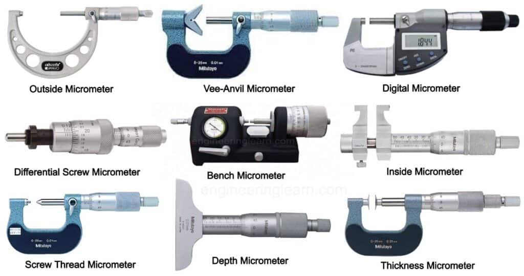
Types of Micrometer / Types of Screw Gauge
1. Inside Micrometer
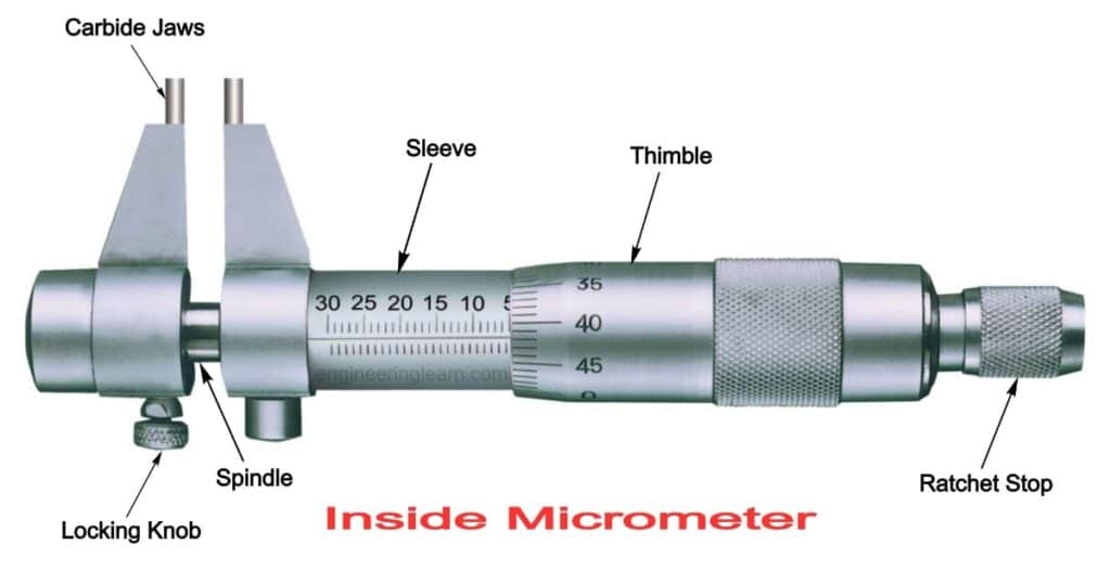
Inside micrometers are generally used for measuring large internal diameters. However they work equally well in measuring the inside diameters of holes and registers. Their shape resembles a pen and there is a thimble in the middle which turns. The micrometer expands whenever the thimble turns. Thimble will expand until it touches the inside of the pipe and the numbering system is used to find out the measurement on thimble. In this micrometer, good quality of steel is used for spindle and measuring head. For the face tool high grade steel is required.
2. Outside Micrometer
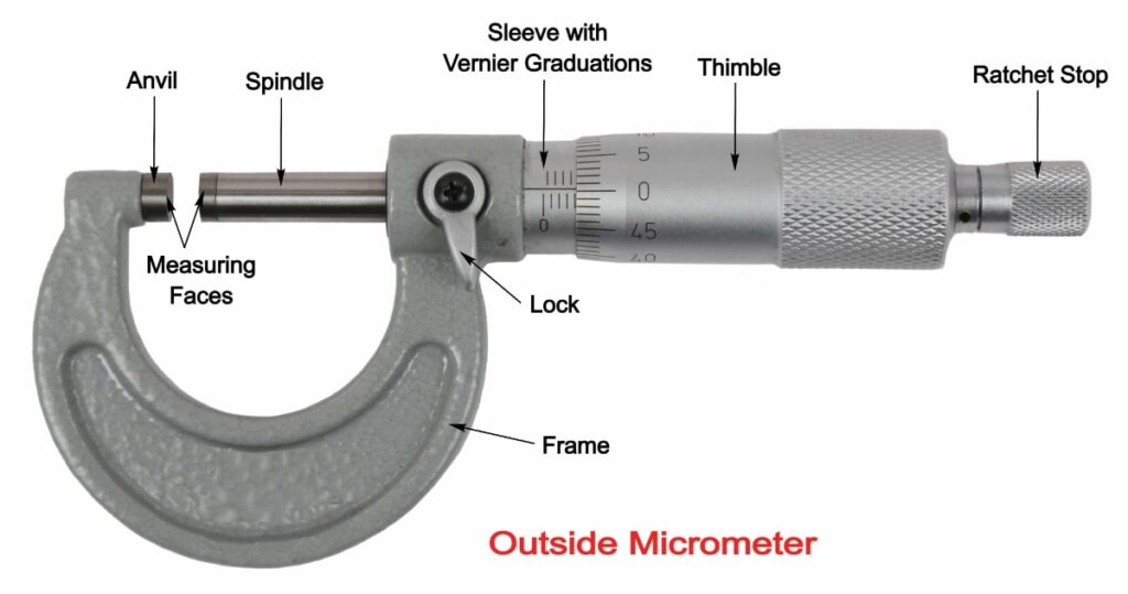
Outside micrometers or external micrometers are used for measuring dimensions of components which are small and where relatively high level of accuracy is required. These micrometers provide direct readings. They are manufactured in different patterns in order to make them suitable for different applications.
These micrometers are used to measure the outside dimensions of a workpiece.
3. Differential Screw Micrometer
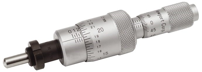
The precision of a differential screw micrometer is higher than that of a standard micrometer because it employs the differential screw concept. In this micrometer, the screw has two kind of pitches, one smaller and the other larger, rather than one uniform pitch as in a standard micrometer. Both screws of the differential micrometer are right-handed, and the screws are placed so that with the rotation of the thimble one goes forward, while the other goes backward. The anvil is not linked to the thimble; instead, it glides into the sleeve. The smaller screw nut is attached to the anvil, while the bigger screw nut is attached to the sleeve, causing the screw to rotate with the thimble.
4. Universal Micrometer
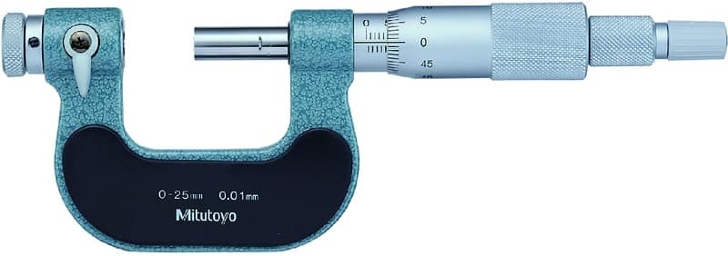
This type of micrometer has anvils which are interchangeable like spherical, flat, disk, spline, blade, knife edge and point. The term universal micrometer is given to them because of their frame which consists of modular components which allow one micrometer for multiple-functioning, that is, as a depth micrometer, outside micrometer step micrometer etc.
5. Blade Micrometer
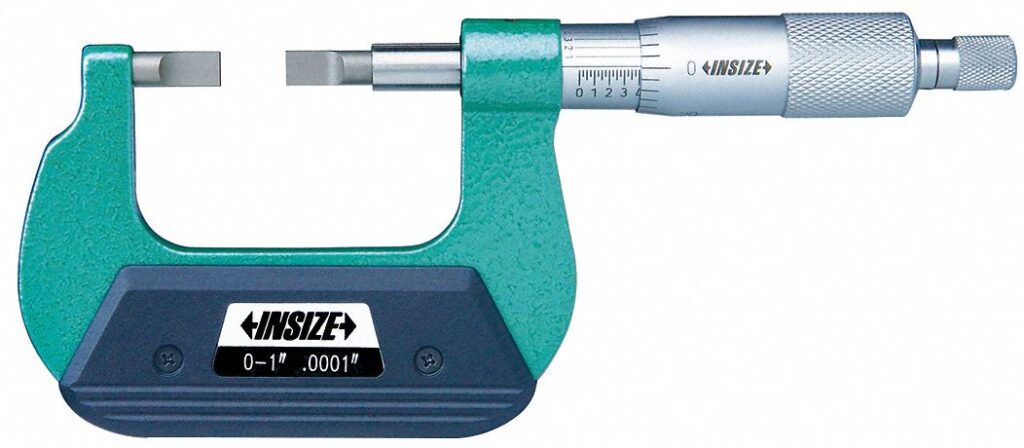
This type of micrometer consists of narrow tips matching set which help it for the measurement of o – ring groove which is a narrow groove.
6. Screw Thread Micrometer or Pitch Diameter Micrometer
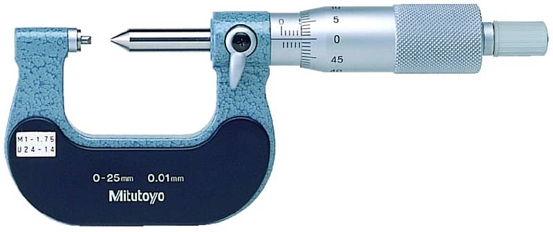
These types of micrometers have thread shaped tips matching set for the measurement of pitch diameter of the screw threads and they are very accurate. They are very similar to ordinary micrometer but the only difference is that they have special spindle and anvil. They anvil have internal vee which can fit at the thread and can rotate freely therefore vee can adjust to various rake range of thread. The spindle has ground conical shape and when it is in contact with anvil’s vee then the micrometer read zero which depend on thread which is to be measured, various types of anvils are provided.
7. Limit Micrometer
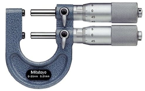
Limit micrometers have two spindles and two anvils and they are used as a snap gauge. The parts are checked and should pass with first gap and stop at second gap to satisfy the specification criteria. The two gaps precisely represent the bottom and top of tolerance rage.
8. Bore Micrometer
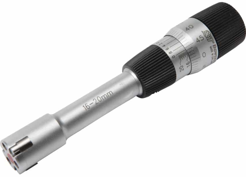
These micrometers generally consists of three anvil heads at the micrometer base which are used for accurately measuring the inside diameters.
9. Ball Micrometer / Spherical Face Micrometer
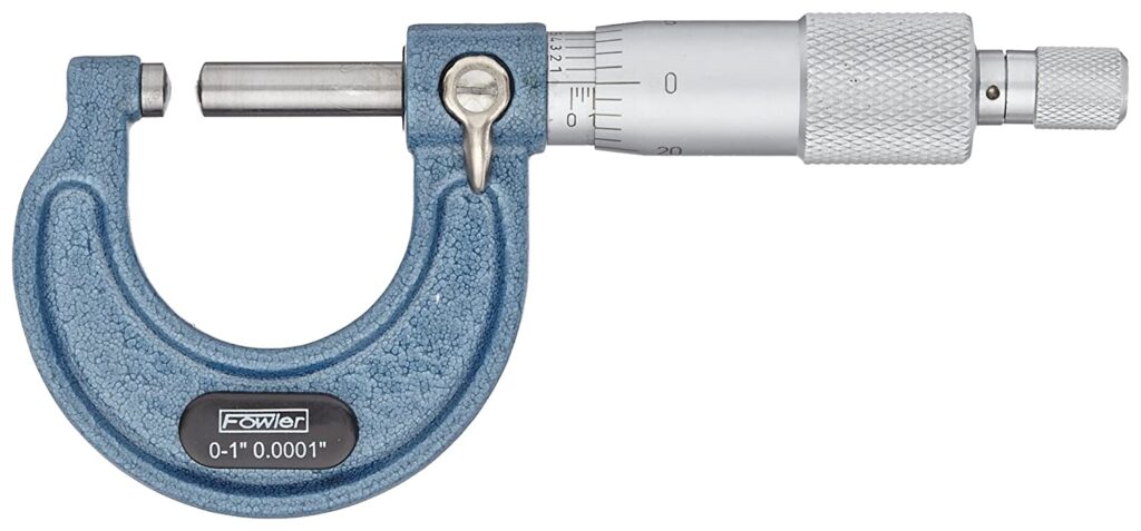
These micrometers have their anvils of spherical or ball shape. They may have one ball anvil and a flat anvil and they are used for the measurement of the thickness of tube wall, distance of edge to the hole and the distance in which anvil are placed on round surface. Ball micrometers are different in application from the tube micrometer because tube micrometers are used for the measurement of rounded surfaces instead of tubes, but ball micrometer are unable to fit in a small tube. Ball micrometers can be used with a pair of balls for single tangential point contact requirement in both sides. In general these are used for the measurement of screw thread’s pitch diameter.
9. Bench Micrometer
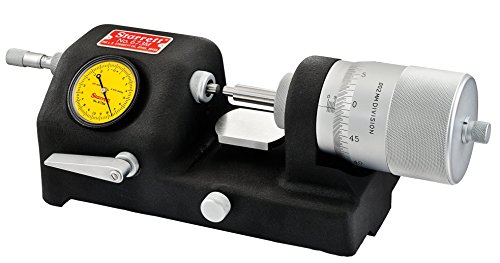
These micrometers are used for the inspection and high precision and accuracy work which is around half a micrometer. This micrometre are based on the principle of magnifying technique and the 0.01 mm gap between anvils are equal to division width of thimble of 1 mm. therefore the real distance are magnified with 100 times. Larger the diameter of thimble larger the modification is possible.
They provide better accuracy because large diameter has large number of divisions in large circumference. They are more reliable and the effect of error is very small. But the only disadvantage in bench micrometer is that they can only be used for comparison purpose and are highly sensitive.
10. Digital Micrometer
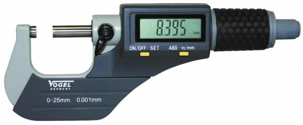
These micrometers use encoder for the detection of the distance and then display result to the digital screen. To avoid the human error in the measurement of the dimensions, the digital micrometer is used for the purpose. The digital micrometer gives direct reading of the measurement.
11. Depth Micrometer
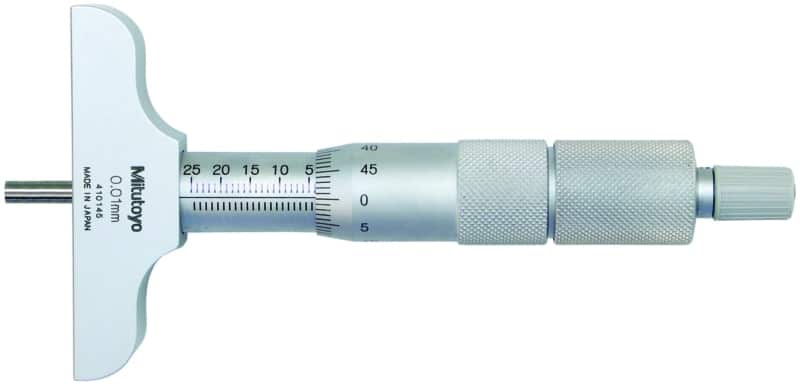
These types of micrometers are used for the measurement of depth of slots, holes and recessed areas. They have a shoulder which can be used as a reference surface and they are firmly held and orthogonal to the hole’s centre line. For the measurement of large ranges, use of extension rods is required. Screw in the micrometer depth gauge varies from 20 mm to 25 mm. length of micrometer depth gauge can vary from 0 to 225 mm. The extension rods are inserted from top of the micrometer and the rod are marked between every 10 mm therefore they are clamped to any position.
12. Thickness Micrometer
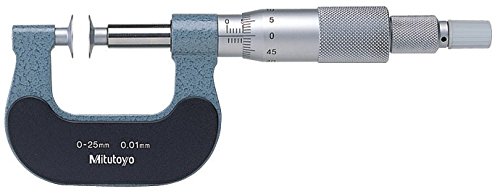
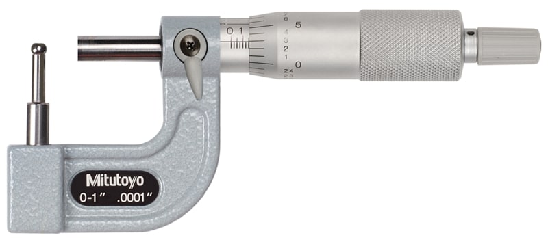
These micrometers are well suited for the measurement of cylinder or sleeve because they cannot be measured from ordinary micrometer. Therefore they are used for measurement of cylinder wall’s thickness and for this purpose there is anvil are provided in which there are spherical measuring surface of frame are cut on outside for permitting anvil in the tube of diameter, minimum diameter from 5 mm. the shape of the anvil is cylindrical and the axis of the anvil should be orthogonal to the axis of the spindle. Therefor thickness micrometers are widely used for the measurement of the tubes of inside diameter less than 12 mm.
13. Vee-Anvil Micrometer
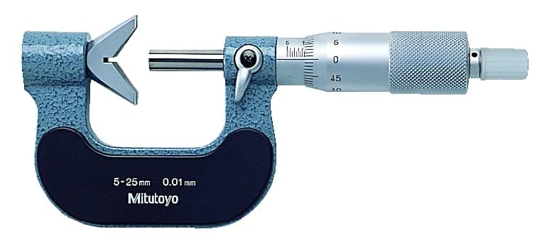
The outside micrometers are the ones in which a small V – block is provided for anvil. They are used for the measurement of the diameter of circle from three different points which are spaced evenly around the micrometer. For example they are used for the measurement of diameter of 3 flute twist drills and end-mills.
14. Tube Micrometer
15. Vernier Micrometer
This micrometer has highest accuracy in the group of micrometers. It can measure with an accuracy of 0.001. The main scale is graded with two sets of division markers on the barrel. The set to the left of the reference line reads in mm, whereas the set to the right of the line reads in 1/2 mm. ( Types of Vernier Caliper )
A thimble scale with 50 equal divisions is graded on the thimble. Each thimble division represents 1/50 of the main scale’s minimum division. 1/2 mm is the minimal division value on the main scale.
On the sleeve, there is a vernier scale. The vernier on the sleeve has ten divisions, which corresponds to nine divisions on the thimble. As a result, one division on a vernier scale equals 9/10th of a thimble. On the thimble, however, one division equals to0.01 mm. As a result, on a vernier scale, one division equals to the least count of the micrometer.
Least count = value of one division of thimble – value of one division on Vernier = 0.01-0.009 = 0.001.
Precautions of Reading Micrometer
- The micrometer comes in a variety of sizes and ranges, and the appropriate micrometer should be chosen based on the size of the workpiece.
- Dust should be removed from the micrometer, and the spindle should move freely.
- Before measuring, check and set the zero reading.
- The workpiece to be measured must be held in the left hand, while the micrometer must be held in the right.
- Ensure that the dimension being measured is parallel to the spindle and anvil axes.
- While making final adjustments, always use the ratchet, and when collecting readings, always use the locknut.
- When measuring diameter, make sure the anvil and spindle sides only come into contact with the maximum dimension.
