Flow Control Valve: Definition, Types, Components & Working Principle
What is Flow Control Valve?
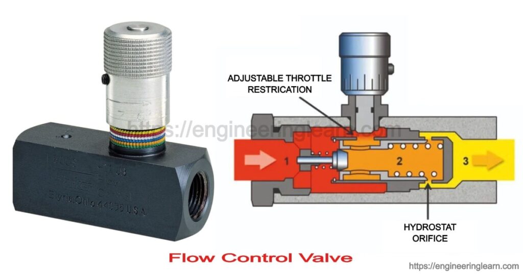
Flow Control Valve: Definition, Types, Components & Working Principle :- Flow regulating valves are also known as speed control valve. The primary function of the flow control valve is flow control in a pneumatic system and regulates the pressure of flow of fluid. Flow control valves in hydraulics are used for controlling the volume of fluid which is supplied to different parts of the hydraulic system.
The speed of the actuators which is being used in the hydraulic circuits can be controlled by regulating the fluid flow, to carry out this regulation operation we need devices and the device which is providing that regulation operation is flow regulation valves.
Compensation of Temperature Change in Flow Regulating Valves
In addition to the pressure compensation the hydraulic systems are having the temperature problem as well, lot of moving components are there and the friction of the moving components is generating the heat energy. As the temperature is increasing that is affecting the viscosity of the hydraulic fluid, the viscosity will be reduced. As the fluid viscosity is reduced, flow rate is changed. By reducing the area of valve opening, the fluid flow can be reduced and by increasing the area of the valve opening fluid flow can be increased.
Flow Regulating Valve Example in Daily Life ( Tap)
Household tap is a very common example of flow regulating valve. Flow regulating valve in household tap contain flow adjustment screw having a ball. By rotating the flow adjustment screw, orifice area can be varied. If the area is reduced then the flow would be restricted or minimized. As the area of orifice is increased by rotating the flow adjustment screw more amount of fluid will pass through the passage.
Components of Flow Control Valve
1. Valve Body
It is also known as shell. It is used as primary pressure boundary of valve. Everything is being hold together by the framework called valve body. The inlet and the outlet piping is received into it with the help of bolted, welded joints. It is cast into various shapes in which the cylindrical and the spherical is the economical one.
2. Valve Bonnet
It is the cover provided for the opening in the body of valve. The body is split in two parts which is bolted together. Some valve bonnets used as a valve covers only while some of them are used for support valve internal accessories like actuator, stem and disk.
3. Valve Trim
It is referred to the elements which is present in internal of a valve. It consists of stem, sleeves, seat and disk. The performance of the valve can be ascertain by seat and disk interface.
4. Disk and Seat
Disk is a element which allow and restrict the fluid flow. When disk is at closed state then total system pressure is exerted on the disk and the outlet side is depressurized. Seating surface for a disk is provided by the seat.
5. Stem
It is that element which is responsible for the connection of actuator and the disk and keeps the disk in its position. The connection of stem with the disk is done with the help of threaded or welded joints. There are two types of stem non- rising stem and rising stem. In rising stem when valve is open then the stem will rise above actuator. And in case of non rising stem there is not any upward movement of stem.
6. Valve Actuator
It is the element by which stem and disk assembly is being operated. It can be operated manually or by electric motor.
7. Valve Packing
This element is used for packing in valves which in result prevents the leakage between stem and bonnet.
Different Types of Flow Control Valves
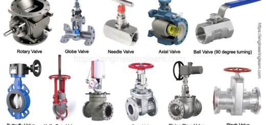
1. Plug Valve or Globe Valve: ( Types of Flow Control Valves )
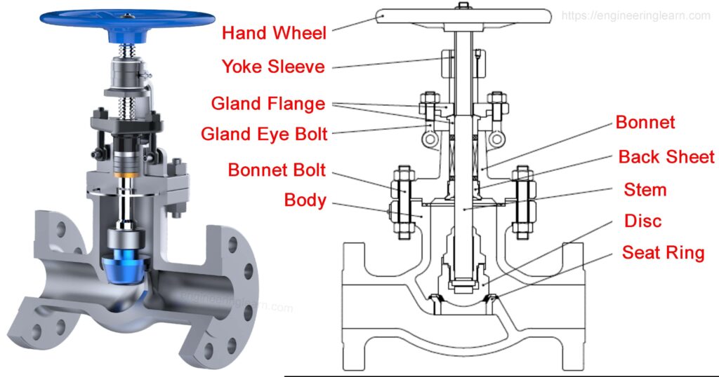
The plug valve is also called as globe valve. Plug is a tapered cylindrical component and this tapered component is placed in between the passage of the fluid flow. The position of the plug inside the fluid flow is controlled by a flow adjustment screw, as we rotate the flow adjustment screw there is movement of plug inside the passage. The accuracy of fluid flow is dependent upon the accurate machining of the tapered angle of the plug, the adjustment of the plug is altering the orifice size.
Stopcock is a typical example of the plug valve which is generally used in laboratory glassware. The body of valve is made up of Teflon or glass while plastic or glass is used for making the plug.
2. Butterfly Valve: ( Types of Flow Control Valves )
The construction of the butterfly valve consists of a disc which is used which can rotate inside the pipe. As we change the orientation of the disc, orifice can be controlled easily; area of the passage can be controlled of fluid flow inside the pipe. Disc is rotated by using electric motor or by manual operation which can easily change the passage. The angle of the disc determines the restriction.
In general the flexibility of rubber is used by the resilient type of butterfly valve and it has the lowest pressure rating. The butterfly valves can be made of any size and they are widely used to flow of liquid as well as gases. In butterfly valve there is constant pressure drop although we will hold the disc in parallel directions to the walls of the pipe then also there would be pressure drop. The discs of butterfly valve are generally made up of plastic or steel (in general stainless steel is used) and if nickel is added they offers high corrosion resistance. Butterfly valves are used because of their less cost and lighter weight.
3. Ball Valve: ( Types of Flow Control Valves )
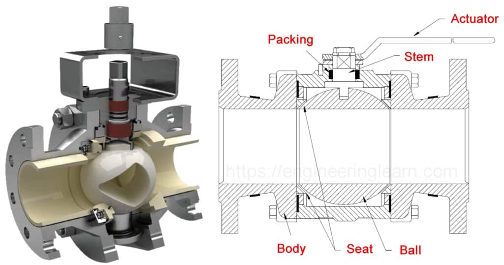
Ball valves are widely used by the industries due to their versatility, high supporting pressures up to 1000 bar can be sustain by this ball valves and they can work at a very high temperature as well up to 250 degree Celsius. In this valve a ball is rotated inside a machined seat, the ball is a floating ball and the ball is having passages as well through which the fluid is passing.
The ball valve is operated by a lever and the lever is having a stem, as the lever is rotated ball is also getting rotated and then we can easily have the passage of fluid through perforated ball. If the passage is in line with the passage of body then the fluid will pass otherwise if the passage of ball is not in line with passage of the body then it will shut the fluid flow. The ball valves are widely used for the shut off applications. These kind of valves are used for high pressure applications.
Components:
1 – Body
2 – Seat
3 – Floating ball
4 – Lever
5 – Stem
4. Balanced Valve: ( Types of Flow Control Valves )
The balanced valves have two plugs, if there is only one plug and one stem arrangement then there may be chances of having excessive thrust on the stem body and due to that excessive thrust there may be more wear and tear more damage to the stem of the valve to avoid that two plugs is used Plug 1 and Plug 2 both these plugs are precisely machined and spool is housing Plug 1 and Plug 2. The spool with Plug 1 and Plug 2 is restrained on Seat 1 and Seat 2 the corresponding Seats are provided for Plug 1 and Plug 2. The entire arrangement is kept inside the passage of the fluid, the pressurized fluid is coming and then it is passing through the passage provided by the Plug 1 and Plug 2.
If upward moment is provided to the spool there would be a gap and the pressurized fluid will pass through the gap. As the pressurized fluid is passing there is application of pressure on the stem on left side. The pressurized fluid which is coming in right side this will also apply pressure on the stem in the opposite direction, that dynamic reaction on the actuator shaft in the opposite direction is balancing the pressure applied by the fluid in the forward direction due to this application of pressure on the stem is balanced and reduce the damage to the wall.
Disadvantages of Balanced Valve
However this type of balanced walls are having the problem of leakage because the tolerances which are provided on the Plug 1 and Plug 2. If there are imperfections in the machining of Plug 1 and Plug 2 then there is leakages from Plug 1 and Plug 2 therefore the machining of the taper of Plug 1 and Plug 2 and tolerances are to be tightly maintained during the machining process.
How Flow Control Valve Works?
Fluid flow can be varied or can be controlled by varying the area through which fluid is passing. When fluid flow is controlled there is pressure drop and this pressure drop is to be considered during selection of a flow control valve. In typical hydraulic circuit there is a pressure fluctuation at the load, sometime higher and sometime lower load. However the inlet pressure is constant, the pump is giving fluid at a constant pressure but the outlet pressure may be different.
To take care of these fluctuations in the load either we can have pressure compensated pumps or we can have pressure compensated flow control valve. Pressure compensated flow control valve can keep the flow rate constant even with the variable load. These pressure compensated flow control valve may have spool and by changing the position of the spool we can change the area of the passage and accordingly the required flow can be maintained during the flow of fluid through the device i.e., control valve.
Image Source :- Controlsdrivesautomation, Parker
