Orifice Meter (Orifice Plate): Definition, Types, Parts, Application, Working Principle, Components, Advantages & Disadvantages
What is Orifice Meter?
Orifice Meter (Orifice Plate): Definition, Types, Parts, Application, Working Principle, Components, Advantages & Disadvantages :- An orifice is defined as the device which is used for measuring the rate of flow of a flowing fluid, for restricting flow or for reducing pressure through a pipe. They generally consist of orifice plate, meter tube and orifice plate housing.
General Description of Orifice Meter
In orifice meter, there is a orifice plate which provides restriction to the flow of fluid. Orifice is placed between the pipes which contracts the streamline due to the contraction of area. Minimum area cross section is known as vena contracta. Orifice diameter is generally kept around 0.5 times of the diameter of pipe but sometimes it can vary between 0.4 times to 0.8 times of the diameter of pipe.
Across the orifice plate differential pressure is developed which is directly proportional to flow rate of the fluid. Orifice meter are generally made up of carbon steel.
Parts of Orifice Meter
1. Orifice Plate
Orifice plate is the plate which have diameter equal to the diameter of pipeline in which there is a drilled hole in it which helps in reducing the rate of flow therefore the pressure can be reduced.
2. Inlet
Inlet is the point at which fluid enters from pipeline and fluid changes its pressure as well as velocity.
3. Overflow Pipe
Overflow pipe are used for the prevention of overflow of glass cylinder.
4. Flow Dissipater
Flow dissipater in the orifice plate are responsible for the flow dissipation which is done by taps and therefore pressure changes.
5. Outlet
Outlet is the point in device at which fluid exits.
6. Pitot Tube
It is used for measuring the pressure drop.
7. Manometer
It is the device which is provided for pressure measurement.
Components of Orifice Meter
1. Orifice Plate
Orifice plate is located between the inlet and outlet section. It is generally used to produce pressure drops which allow them to measure the flow rate.
2. Flow Conditioner
Flow conditioner is installed at the inlet section and is used for enhancing the linear flow at the inlet section.
3. Outlet Section
Outlet section are also a linear segment and used for determining the pressure of liquid or gas discharged.
3. Inlet Section
Inlet section is the linear segment which is extended from device and inlet section act as end connection for the flowing fluid.
Working and Operation of Orifice Meter
The working of the orifice meter depends on the principle of differential pressure measurement. The gas or liquid whose rate of flow need to be determined are passed through orifice which results in drop of pressure across the orifice plate which vary with rate of flow and then results in differential pressure between inlet and the outlet segment. This drop in pressure is measured and then this drop in pressure are measured and used for the calculation of rate of flow of the gas or fluid.
Let d1 is the diameter at the section 1
D2 is the diameter at the section 2
P1 is the pressure at the section 1
P2 is the pressure at the section 2
V1 is the velocity at the section 1
V2 is the velocity at the section 2
A1 is the area at section 1
A2 is the area at section 2
Now by applying Bernoulli’s equation at section 1 and section 2, we have
P1/ ρg + v1²/ 2g + z1 = P2/ ρg + v2²/ 2g + z2
{P1/ ρg + z1} – {P2/ ρg + z2} = v2² – v1²/ 2g
h = v2² – v1²/ 2g
v2 = √(2gh + v1²)
Where h is the differential head.
Let A˳ be the area of orifice
Now coefficient of contraction, Cc = A2/ A˳
Therefore by continuity equation,
A1V1 = A2V2
V1 = A˳Cc x V2 / A1
Now, V2 = √{2gh + (A˳² Cc² V2²/ A1²)}
V2 = √(2gh)/ √{1 – (A˳² Cc²/ A1²)}
Thus, discharge
Q = A2V2 = V2A˳Cc = A˳Cc√(2gh)/ √{1 – (A˳² Cc²/ A1²)}
If we have Cd is the coefficient of discharge for the orifice meter
Cd = Cc x √(1 – A˳²/ A1²)/ √(1 – A˳² Cc²/ A1²)
Cc = Cd x √(1 – A˳² Cc²/ A1²)/ √(1 – A˳²/ A1²)
Therefore,
Q = Cd x A˳A1 √(2gh)/ √(A1² – A˳²)
The value of coefficient of discharge of orifice meter is very less in comparison with the value of coefficient of discharge of venturimeter.
Types of Orifice Fitting
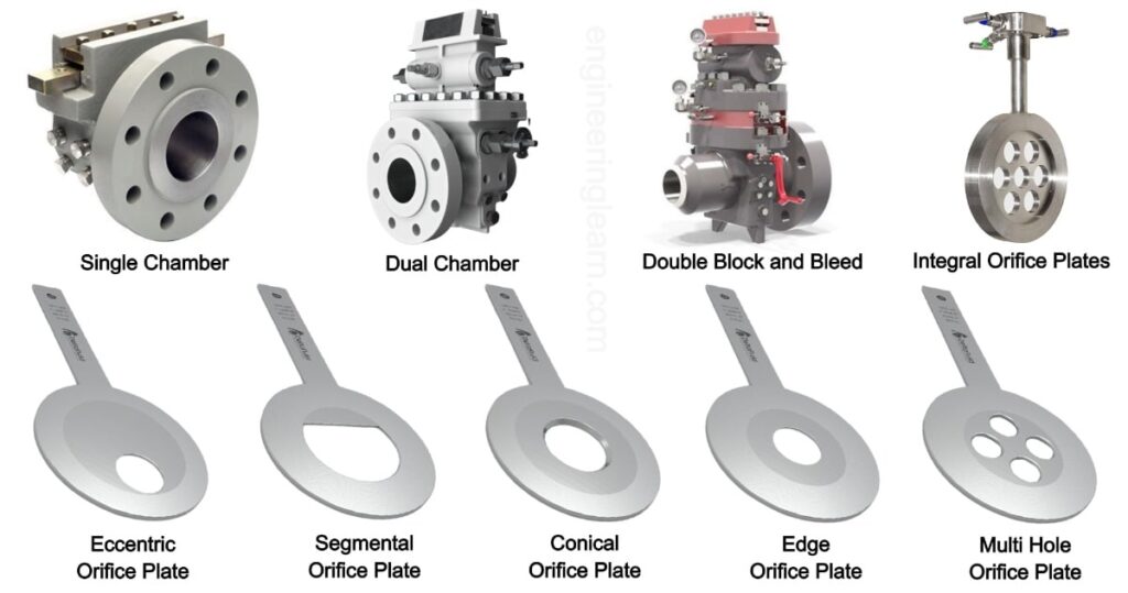
There are generally three main types of orifice fittings
1. Double Block and Bleed
They contain two different valves of different chambers which increase the operational safety. They also provide protection from the liquids which are toxic in nature.
2. Single Chamber
It have single chamber which is designed for accurate measurement of the rate of flow of the gas or fluid.
3. Dual Chamber
Dual chambers are installed in conjunction with upstream and downstream sections and they have a O ring seal which eliminate the issue of the maintenance of gasket. In addition, a valve seal is also provided for this type of orifice fitting.
Types of Orifice Plates
Standard shape of the orifice plate is bevel or cone, on the smaller side they have sharp edges and edges are face to the upstream of the flow. Orifice plates can be used for huge variety of pipe diameters.
There are various types of orifice plate used in orifice meter
1. Eccentric Orifice Plate
In eccentric orifice plate the hole is off the center. They are generally used for those liquids which contains solids or gases.
2. Concentric Orifice Plate
In this type of orifice plate the hole is at the center. These orifice plates are most common among other types of orifice plate. They are used for various of process but generally not used for highly corrosive process or slurries.
3. Integral Orifice Plate
These type of orifice plates are generally used for low rates of flow. They are small tube which is mounted directly over the differential pressure transmitter. They have an orifice which is present inside the tube and are used for connecting the high side of the cavity to the low side of the cavity.
4. Segmental Orifice Plate
The segmental orifice plate is a slender plate with an opening in the shape of a circular section.
5. Others Like Quadrant and Conical, Edged Entrance
Conical orifice plates generally installed on backwards therefore flow enters through the beveled side instead of entering through the non beveled side.
Application of Orifice Meter
It is used in following industries:
- Refineries
- Natural gas industries
- Petrochemical plants
- Water treatment plants
- Oil filtration plants
Advantage of Orifice Meter
- They are cheap in comparison to other devices like venturimeter.
- They need less space for their installation; therefore they are ideal for space constrained applications.
- They can be used in large pipes also for the determination of flow rates.
- They can be installed in vertical as well as in horizontal positions.
Disadvantage of Orifice Meter
- They can easily clog if there are impurities present in gas or liquid.
- They have low discharge coefficient.
- The orifice plate is corroded easily with time.
- To attain streamline flow, flow straighteners are needed at the outlet and inlet which increase the space for installation as well as cost.
- In orifice meter, downstream pressure cannot be recovered and the head loss is in between 40 percent to 90 percent of differential pressure.
Image Source :- deltafluid, lsproline
