Plate Fin Heat Exchanger [Complete Details] Definition, Working, Applications and Concepts
![Plate Fin Heat Exchanger [Complete Details] Definition, Working, Applications and Concepts](https://engineeringlearn.com/wp-content/uploads/2021/12/Plate-Fin-Heat-Exchanger-1024x539.jpg)
What is Plate Fin Heat Exchanger?
Plate Fin Heat Exchanger [Complete Details] Definition, Working, Applications and Concepts :- A plate-fin heat exchanger is referred to as a type of heat exchanger which is specifically designed that is found using plates as well as finned chambers in order to transfer the heat within the fluids. These are some of the commonly known and are thus categorized as a compact heat exchanger which emphasize its relatively high heat transfer surface area to volume ratio respectively. This particular heat exchanger is known to have wide usage in the industry which includes the aerospace industry in its compact size as well as is found having a lightweight property where mostly its ability is to facilitate the heat transfer accompanied with the small temperature differences which is found to be utilized.
Aluminum alloy heat exchangers are referred to as those plate fins which can be termed as Brazed Aluminum Heat Exchangers and are known for being used in most of the aircraft industry. It is also known to be adopted into the cryogenic air that is found separating the industry around the time of the second world war. These are also found being used in railway engines as well as motor cars. Stainless steel plate fins are found to be responsible for being used in the aircraft for over 30 years which are now found becoming an established channel in the chemical plant
Various Concepts of Plate Fin Heat Exchanger
There are various concepts of plate fin heat exchanger. It is important to know that the corrugated metal fins are found being placed within the flat plates. The structure is found to be joined together using a brazing. These are the fins which are found having the dual purpose of holding the plates together which are responsible for containing the pressure and thus forms a secondary (fin) surface for the regular transfer of heat. The edges of the plates are found having bars which mostly contain each fluid within the space that is found within the adjacent plates.
The heights of corrugations accompanied with the bars can vary within the plates. A liquid stream is commonly found to be used for the purpose of low height corrugation that is found matching the high heat transfer coefficient which gets accompanied with a lesser surface area while for a low pressure stream which can be used as a high corrugation height that matches the low coefficient along with the higher surface area but also gives larger through area in order to achieve the lower pressure drop. An industrial unit is found being responsible for containing about 1000 m2 of surface per cubic meter.
Basic Construction of Plate Fin Units
- Aluminum units are referred to as those units which can be made up to 1.2 m × 1.2 m cross section and 6.2 m long.
- Stainless steel units are found having the dimensions as 500 mm × 500 mm cross section × 1500 mm length.
Corrugations (Fins)
- Plain corrugation is known to be the basic form as it is used normally for the low pressure drop streams.
- Perforated corrugation is responsible for showing a slight increase in the performance over a plain corrugation whereas it is found to be reduced by the loss of area due to the perforation. The main purpose is to permit the migration for the fluid across the fin channels which is usually in boiling the duties.
- Herringbone corrugation is found being made by displacing the fins sideways at every 9.5 mm in order to give a zigzag path. The performance seems to be intermediate within the plain as well as serrated forms. The friction factor is responsible for continuing it in order to fall at a high Reynolds numbers which shows its advantages at higher velocities as well as pressures.
Construction of Plate Fin Heat Exchanger
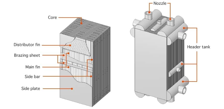
Plate-fin units are referred to as the ones which are normally found to be arranged for the counter flow heat exchange. Cross flow units are the ones which are commonly used for the vehicle radiators and also cross counter flow is used for the liquid sub coolers.
The arrangements of the typical layer for a three-stream heat exchanger can be known wherein a two-stream exchanger is found to be constructed by using the first of the arrangements that can be shown for the hot stream also and also alternating along with the second arrangement which can be shown for the cold stream.
This is the way by which the heat exchanger is found to be built up to an appropriate height. After which it is found to be brazed together wherein the headers and the pipework are found to be welded over the inlet as well as the outlet parts of each stream in order to give a finished unit. Layers are found to be normally arranged accompanied with an alternating hot as well as cold streams. An alternative system can be referred to as a double banking whereas a three-stream unit is found being made by using all the fin arrangements.
Characteristics of Plate Fin Surfaces
There is a method by which a stream is found occupying layers at one end of a block which is found to take out at part length and get replaced by other stream at the other end of the considered block. This step can be repeated wherein the ethylene exchangers are found to be responsible up to 5 streams which usually occupy the same layers for different lengths.
There is a variation of the system which is responsible for allowing a part of a stream which needs to be taken out at part length. There is a use of all these features which permits a high degree of process intensification for a single block. There is a maximum number of streams found in one block which is commonly known to be ten out of which three had partway take-offs or additions.
Brazing and Materials
Aluminium units are found useful material in the exchanger block. The material of braze if known to be silicon. There are plates which are found to be purchased within a thin film of braze metal on both of its sides. The unit is usually found to be built and is thus placed in a vacuum furnace. Braze can take place under the presence of vacuum and that too at a temperature difference of 580°C. The parts of the block after this are then firmly attached together.
Stainless steel units are found being made of the AISI type 321. Braze material is known to be quite essential as nickel which can be applied at the plates by spraying. Brazing takes place under the influence of vacuum at varying temperature up to 1050°C.
Pressures and Temperatures
Aluminum units are found being operated with the design pressures that is found varying up to 100 bars at temperatures from absolute zero to 65°C. Above the temperature 65°C a change of header material needs to allow operation to 120°C which can reduce design pressures. Stainless steel units are found to currently limit it to 50 bars design pressure and then the temperatures up to 750°C.
Plate Heat Exchangers
A plate exchanger is referred to as the one which consists of a series of parallel plates that are found being placed one above the other in order to allow the formation of a series of channels.
The space which is present within the two adjacent plates is responsible for forming the channel in which the fluid is found to flow. The Inlet as well as the outlet holes at the corners of the plates are responsible for allowing the hot as well as cold fluids through the alternating channels in the exchanger to keep the plate in contact on one side along with the hot fluid and the other with the cold.
The regular size of a plate can normally vary from a few square cms. to few square meters. The number of plates which are found in a single exchanger is found ranging from around ten to several hundred, so that it reaches the surface exchange areas up to thousands of square meters.
Usually the fluids are responsible for dividing it into several parallel streams which can produce a perfect counter current. These are the corrugated plates which are used in order to increase the turbulence so that the thermal exchange surface is done in order to provide mechanical rigidity to the exchanger. Corrugation is found to be achieved by the cold forging of sheet metal accompanied with the thicknesses varying from 0.3mm to 1 mm.
Plate Heat Exchangers
The fluids are usually observed crossing the channel which is meant for that, in either series or parallel method by making the counter-current or the current configurations. The serial configuration is being used whenever there is a small flow rate for each fluid where there is a high heat jump. The greatest problem which is found is the high pressure drop that can be an example of imperfect counter-current. There are some parallel configuration which are observed along with a counter current channel which is commonly used for the purpose of high flow rates accompanied with the moderate temperature drops wherein these are the ones which seem to be most widely used.
There is a great difference observed within the flow rates or within the maximum permissible pressure drop of the two fluids. The exchanger is observed being run twice by the effect of fluid accompanied with a lower flow or with a higher losses in order to balance the values of pressure drops which specifically flows the rates in the channels.
There are two basic types of plate heat exchangers which are commonly known as Brazed Plate Heat Exchangers and Plate Heat Exchangers.
Plate and Frame Heat Exchangers
In PHE there is found a plate which is responsible for creating a frame where the plates are pressed along with the headers and the tie bars along with which the seal is also guaranteed by the gaskets. In addition to their effect of sealing the gaskets are also responsible for serving the direct flow of the fluids which are placed along with the grooves at the edges of the plates.
The maximum temperatures which is considered for the purpose of sealing the heat exchangers is found within 80°C to 200°C whereas the pressures can also reach up to 25 bar.
Gaskets are found to be available in various different types of butyl as well as silicone rubber. The main characteristics of such types of heat exchangers are as follows:
- Easy as well as quick dismantling for cleaning and control operations is possible.
- Adaptation of variable operating conditions by the addition or subtraction of heat plates in order to modify the installed thermal flow
- Any fluid which is found to leak due to the effect of non-perfect sealing of the gaskets may not contaminate the other fluid as these are directed away.
- Whichever materials are poorly adapted to soldering like titanium are found to be used commonly.
- There is a gaskets limit in terms of maximum pressure as well as temperature values.
- Potentially there is a high cost due to the design of moulds that presses all the production process.
- High cost of the gaskets is observed.
Brazed Plate Heat Exchangers
- Brazed plate heat exchangers are referred to as such types of exchangers which are found having no headers, tie bars or sealing gaskets as the plates are found to be furnace brazed at temperatures of approximately 1100°C.
- While the process of assembly phase takes place there is a sheet of brazing material which is usually of the material copper or nickel is found being placed within the plates, for this the pack is found being pressed and are subsequently baked for few hours.
- The best part of BPHE exchanger is that it is found to be more compact, lighter as well as less bulky as compared to the ones with gaskets. The path is also found made by the hot as well as cold fluid.
- The brazing material is found responsible which carries out the function of both the gaskets as well as the frame. These exchangers are the ones which are commonly used along with the chevron corrugated plates and are thus assembled alternating to the corrugation directions so that the lattice contact can be created.
- The crossing points within the corrugations of two coupled plates is the one which is responsible for forming a dense network so that the contact points that confer pressure tightness also induce swirling streams which can improve the heat exchange. This is the way through which the turbulence of the fluids is found to be high even at the lower nominal input speeds wherein the flow seems to pass from the laminar to turbulent for the lower flow rates. These are some of the immediately noticeable paths which are found to be made by the fluids is chaotic so the cross section seems to vary continuously.
Brazed Plate Heat Exchangers
- One of the main disadvantage of such type of exchangers is that they are not removable and thus the maintenance as well as the cleaning does not seem to be that easily possible or at least difficult wherein no flexibility seems to exist as the number of plates can in no way be varied. There are various surfaces of the plates which seem to be corrugated so that there can be an increase in the turbulence of the fluid while the flow into the channels continues.
- There is found a corrugation pitch which is denoted by p. The height is denoted by b and angle by β which is compared to the main direction of the flow.
- The inclination of the corrugation plate is responsible for determining the effect on thermal exchange accompanied with the load losses. There is found to be a pair of plates accompanied with a high β angle which seems to be greater than 45 °and thus gives a turbulence which therefore is a high heat exchange along with a higher pressure drop.
- In case the angle seems to be small than 45 ° then it can definitely cause a lower turbulence flow accompanied with a lower heat exchange coefficients that is also responsible for lowering the pressure drops.
Brazed Plate Heat Exchangers
- The research towards a compromising β angle within the high exchange coefficients as well as the acceptable load losses seems to be quite essential.
- The corrugation height b is found having an important effect with respect to the exchange coefficients as a greater depth seems to be responsible which can cause greater turbulence.
- The height as well as the pitch of the corrugations is responsible for increasing the plate exchange surface area i.e. the surface enlargement factor φ needs to be defined which can be defined as follows:
Φ = actual corrugated surface area divided by the projection area corrugated surface
The actual area seems to be difficult in order to compute as it can compare different exchangers that needs the reference which is made so that the projected area can be found.
Image Source :- spp.co.jp
