Axial Compressor: Definition, Working, Components, Construction, Applications, Advantages & Disadvantages
Definition of Axial Compressor
Axial Compressor: Definition, Working, Components, Construction, Applications, Advantages & Disadvantages :- In an axial flow compressor, air gas is radially entered into the rotor or impeller and is axially discharged from the compressor. Hence is known as the axial compressor. As the compressor is based on rotating air blades, it allows gas or other working fluid to flow parallel to the shaft axis. This compressor operates at constant pressure and external physical conditions like density or mass flow rate and inlet temperature have an impact on its power. ( Types of Air Compressor )
Properties of Axial Compressor
Axial compressors are utilized in a wide array of applications like dehydrogenation of propane, fluid catalytic cracking air, air separation units of large capacity, and blast furnace air. Due to their highly flexible operation during flight and high reliability, axial compressors are also used in aircraft engines. Even though these dynamic compressors have a fairly high cost, their price per high flow rate can be significantly inferior as compared to other types of compressors.
Significance of Axial Compressor
It is a very widely known type of dynamic compressor and provides an axial flow of gas or air at a constant pressure. An axial-flow compressor is a type of mechanical device which pressurizes the working fluid continuously. These types of compressors are usually lightweight and small in size as compared to centrifugal compressors but run fairly faster.
Axial compressors are generally used for applications that require a high-pressure flow of gas and low heat. It consists of blades of a particular shape inside a drum. Due to the high speeds of these dynamic compressors, they can generate electricity when combined with a gas turbine.
Working of Axial Compressor
The basic law after the working of an axial flow compressor is that the rotor conducts kinetic energy to the fluid, which is afterwards translated to static pressure when diffused through the passages or when it strikes the rotor blades.
- In an axial flow compressor, the flow of fluids is along the axis. In the beginning, the inlet guide vanes or stator blades are present to ensure that the gases strike on the rotor blades with the proper angle of impact.
- Right next to the stator blade, the rotor is placed. For the striking of gas action, the aero foil shape of the blades here is a crucial feature.
- An axial-flow compressor operates in a number of stages. The rotor and stator altogether constitute one single unit. Typically, there can be as many as five to fifteen stages in the working of an axial flow compressor.
- The number of stages in the operating of an axial flow compressor is determined by the pressure ratio required as well as the amount of gas or fluid.
- The stator and rotor blades are packed alternately. In the starting, the gases hit the stator or the first guide vane, which direct the gases in the direction of the rotating rotor blade that follows next.
- The function of these rotor blades is to increase the kinetic energy of the gases and then transfer it to the adjacent stator blade. Then the gases fall on the stator blades.
- As the gases hit the stator blades, their pressure energy increases, but the gases lose their kinetic energy.
- Now the gases with a decreased velocity will move towards the next rotor, which will increase the kinetic energy of the gases. This new kinetic energy will be significantly lesser than the kinetic energy provided to the gases by the rotor earlier.
- This cycle of multiple processes repeats until the gases reach the exit. The gases exit the compressor at very high pressure.
Components of Axial Flow Compressor
Typically, an Axial Flow Compressor consists of the following components:
1. Rotor
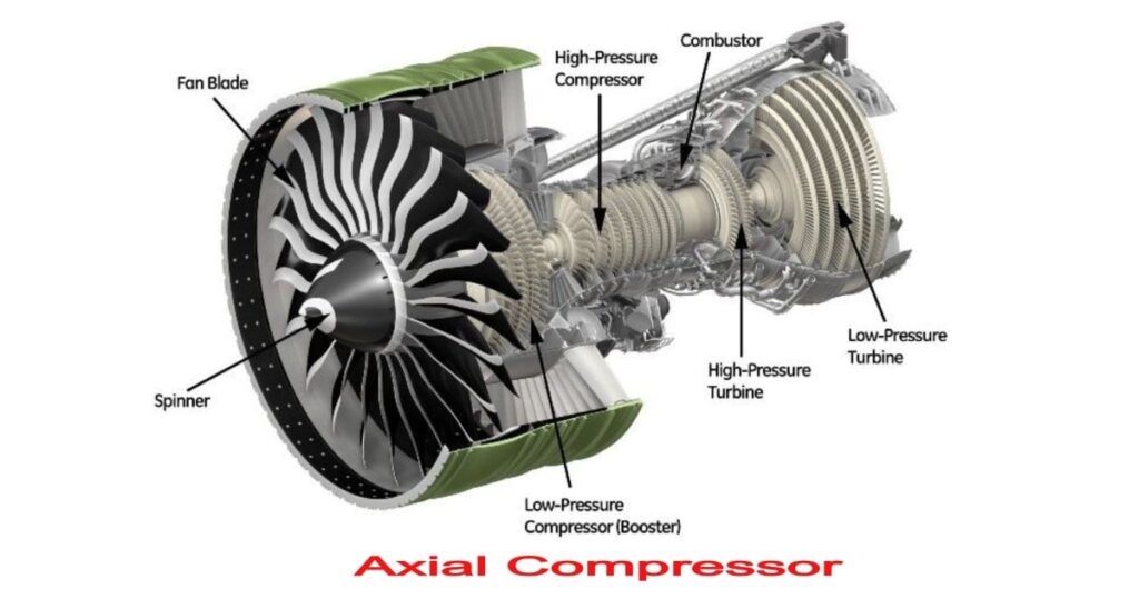
The rotating part of the axial flow compressor is called the rotor. The rotor consists of a rotor drum which is connected to the shaft. The shaft here is the actual rotating element of the device. The shaft imparts the rotary motion to the rotor drum. The rotor blades are also mounted on the rotor drum.
2. Casing
The casing acts as an outer protective shield or membrane for the axial flow compressor. Apart from protecting the internal mechanics of the compressor, the casing also performs several other functions. The stator blades of compressor are mounted on the casing. These are the fixed blades of the axial flow compressor. The casing is manufactured from the following materials
- Iron or high-quality steel
- Magnesium
- Aluminum
- Titanium
3. Stator Blades
The stator blades are different from the rotor blades which rotate with the rotor drum. They stay motionless throughout the complete compression process. They are mounted on the casing of an axial flow compressor. The stator blades are manufactured from the following materials
- Composites
- Titanium
- Steel
- Nickel alloy
4. Rotor Blades
Rotor Blades are mounted on the rotor drum. These rotor blades rotate and are also responsible for increasing the kinetic energy of gases or fluids.
Some of the materials used for the construction of Rotor Blades are as follows
- Composites
- Titanium
- Steel
- Nickel alloy
Construction of Axial Flow Compressor
- Supplementary row of fixed vanes called inlet guide vanes are fixed at the inlet of the compressor, which serve the purpose of guiding the air to hit at the accurate angle on the initial row of moving blades.
- To maintain smooth and efficient flow of air through the compressor, the rotor and stator blade banks should be as near as possible.
- The radius of the rotor hub and the length of the rotor blades are designed in such a way that only a very small tip clearance is left at the rear side of the rotor and stator blades.
- One single stage of operation constitutes of a set of rotor and stator blades each.
- Successive sets of blades are built with heights reduced to in a way to compensate for the reduction in volume, which results in increased pressure from one stage to next stage and therefore keeping the axial flow velocity constant throughout the compressor.
- The rotor and stator blades are assemble din such a manner that the spaces between them create deviating passages, therefore the velocity of the air keeps on decreasing slowly as it passes through them, which then results in a rise in pressure.
Applications of Axial Flow Compressor
- Used where a high flow rate is required.
- In aircraft turbojet engines
- Used in ship engines for high speed.
- Used for various industrial applications such as dehydrogenation of propane and blast furnaces
Losses in Axial Flow Compressor
Just like any other mechanical device, an axial Flow compressor, is not devoid of losses. These compressors generally experience the following type of losses.
1. Skin Friction or Annulus Loss
This type of loss arises due to the axial growth of the boundary layer. It is a type of viscous loss and it accounts for approximately 50% of the total losses.
2. Secondary Flow Loss
Secondary flow losses occur when the flow of fluids takes place through curved blade passages.
3. Tip Leakage Flows
Due to the presence of gaps between the casing and the blade, a flow arises from the pressure surface to the suction surface, resulting in losses for the machine.
4. Profile Loss
This loss occurs due to the growth of the boundary and its subsequent separation on the blade profile. That is, due to the peculiarity of their aero foil structure profile losses occur.
Advantages of Axial Flow Compressor
- Higher peak efficiency when compared with other types of compressors.
- Significantly higher mass flow rate. Since the axial flow compressors have a higher pressure ratio, they are very efficient.
- Having multiple stages also helps in having a higher pressure ratio. Even a 40:1 pressure ratio is achievable through an axial flow compressor.
- Reduced aerodynamic drag is achieved due to a small frontal area for a given flow.
Disadvantages of Axial Flow Compressor
- It is difficult to manufacture an axial flow compressor.
- It is an expensive piece of machinery. Due to the heavy weight of the compressor, the installation of this machine is very difficult.
- To start or initiate the compression process, it requires a massive amount of power.
- The reason for employing multiple stages for axial flow compressors is the fact that the pressure rise in individual stages is low.
Image Source :- softinway
