Master Cylinder: Types of Master Cylinder, Working Principle of Master Cylinder, Parts of Master Cylinder
Master Cylinder Introduction:
Master Cylinder: Types of Master Cylinder, Working Principle of Master Cylinder, Parts of master Cylinder: – The master cylinder in a car stopping mechanism is a water-powered device in which chambers and some cylinders are organized in such a way that the mechanical power applied to the brake pedal in a car by the driver or the brake switch in a bicycle is converted to a water-driven load, which is then used for braking by the brake calliper.
An ace chamber is a device in a hydraulic braking system that duplicates mechanical force applied by the driver via the brake pedal or brake lever. It sends the needed weight or braking power to the final braking section. The master cylinder, like the brake disc/rotor, is an essential component of a disc brake assembly.
Types of Master Cylinder
1. Open System
A bladder inside the reservoir tanks makes up an open system master cylinder assembly. These bladders assist in adjusting the braking fluid level in the master cylinders. When one side of the bladder is exposed to the outside, it expands or contracts in response to temperature variations.
2. Closed System
The master cylinder in a closed system does not have a bladder in the reservoir tank. As a result, the system requires manual tweaking.
It is commonly used in all types of autos; you can check the brake fluid level through the reservoir tank and adjust whether it is dark or not between suggested levels by changing whether it is dark or not. Brake pads that are worn out may be identified readily in such systems.
3. Single-cylinder Engine
The most basic master cylinder is a single-cylinder, which is fundamentally identical to a plastic medical syringe. The plunger pistons inside the cylinders are pushed by the brake pedal lever, which causes fluid to flow through the lines and into the slave cylinder. When the brake pedals are removed, springs inside the cylinder push the plunger back to its original position.
Negative pressure draws the braking fluid from the lines and the reservoir into the cylinder. Long ago, automakers shifted to more redundant tandem master cylinders. However, many race car manufacturers prefer to regulate front/rear brake pressure bias with a pair of single cylinders rather than a single tandem cylinder.
4. Master Cylinder with No Port
Portless master cylinders, first seen on the Toyota MR2, enable a speedier brake release than traditional systems that employ a compensating port. When you remove the brake on a portless cylinder, a valve assembly in the piston opens to equalize pressure.
This eliminates the need for a compensating port in the brake cylinders, restricting fluid flow and lowering brake pressure during the first application.
The anti-lock braking (ABS) system, which employs quick pressure modulation to alter braking force, benefits from the fast-reacting portless cylinder.
5. Tandem Cylinder with Ports
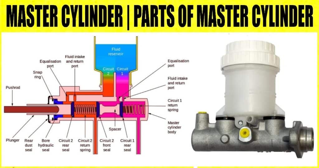
A tandem cylinder has two pistons in one cylinder. The brake pedal is linked to the major pistons. When the brake pedals are depressed, the piston pushes against a spring linked to the secondary piston’s back. The secondary piston begins pushing the fluid through its specialized mechanisms after the spring is fully compressed.
Fluid can flow past the piston through the reservoir inlet port, ensuring uniform pressure on both sides. The spring pressure pulls the piston back when the brake pedals are released, and a tiny compensating port from the brake fluid reservoir introduces extra fluid into the chamber.
Parts of Master Cylinder
A reservoir tank bore, piston assembly, lever or pedal, hosepipe, and other components make up a master cylinder assembly. Let’s take a look at each of these sections independently.
1. Pedal or Lever
This is the section of the master cylinder assembly where you provide the master cylinder instructions.
2. The Return of Spring
This has been observed in drum and disc brake systems. When the brake lever or pedal is withdrawn, the piston returns to its original position.
3. Pushrod
A lever and a piston are connected to the pushrod. The piston is pushed into the bore and slides when the brake lever is squeezed.
4. The Piston
A push rod and a return spring link a piston or MC pistons. The brake fluid moves into the bore when the brake lever or pedals are applied to push it.
5. Piston Assembly
A piston assembly is made up of a piston, a succession of O rings / gaskets called cup / O rings, circle p, primary cup, and secondary cup, as well as a return spring. A piston assembly fills the master cylinders’ bores.
6. Bore
Calliper assemblies and master cylinder assemblies have a bore under which the piston glides.
7. Brake Fluid
Hydraulic fluids include brake fluids. This is just as critical as oil in an engine. It is a device that transmits force under pressure. Brake fluid is categorized similarly to motor oil, with designations such as DOT 3, DOT 4, etc. DOT stands for Department of Transportation.
8. Bladder
The bladder is located in the master cylinder of the open system. It’s comprised of thin-walled rubber that can expand and shrink, allowing it to distort. On one side, it’s liquid, and on the other, it’s air.
9. Reservoir
Aluminum or cast iron is used to make it. It’s full of brake fluid. It features a glass through which you can see the oil level and colour. Reservoirs for rear disc brakes are typically rectangular or square. However, spherical reservoirs are also utilized.
10. O ring / Gasket Series
The cup or o ring, main cup, secondary cup, and circle p are all included. The piston is held by a cup and circle P (also known as a lock ring). They are situated between the piston and the pushrod. The main seal might be in the form of a cup or an O ring. When the brake lever or pedal is squeezed, brake fluid from the reservoir flows over it and into the brake hose pipe.
11. Hosepipes
The braking fluid is transferred from the master cylinder assembly to the calliper assembly through a tube-type conduit.
12. Use a Clamp
The whole master cylinder assembly is included. When the brake lever or pedals are engaged, the piston is pushed by the pushrod connecting to the lever or pedal and the pistons. This action allows the pistons to glide and force the return spring into the master cylinder’s bore, causing pressure to build up in the reservoir tank. The main seal permits the reservoir tank’s braking fluid to flow from the top into the brake hosepipe.
Master Cylinder Principle of Operation
Master Cylinder with a Single Circuit When the brake pedal is not pressed, the cylinder stays in its unique position, sealing the bay valve of the repository and preventing contact with the brake liquid in the Single Circuit Ace Barrel. The pressure chamber is located in the centre of the shop. The cylinder is connected to the brake pedal through the interface pole when the brake pedal is squeezed, allowing the brake fluid to flow from the storage to the pressure chamber.
Because the cylinder inside the barrel is growing like a medicinal syringe, the brake liquid inside the pressure chamber is packed. The outlet valve opens once the brake fluid has been pressurized to a particular load, and this highly pressured brake fluid is transferred to the brake lines for extra brake activation.
The working of the double ace barrel is 70% the same as that of the single circuit mc, but in this type 2, autonomous braking circuits are employed; let’s examine how it works. When the brake pedals are not depressed, the cylinder remains in its unique position, closing the delta valves of both pressure chambers and interrupting the braking fluid flow between the two repository chambers.
The relevant cylinder moves first when the brake pedal is pressed, opening the needed bay valve. Developing the necessary cylinder causes the braking fluid pressures inside the required chamber to rise. When the appropriate chamber pressure is reached, the required outlet valve opens, the packed brake fluid is supplied through the brake lines to the brake callipers, and the required circuit brake is activated.
The auxiliary cylinder starts running after the development of the required cylinder, i.e., at its exceptional end, due to the power attached to the required cylinder’s spring, which opens the alternator valve and approaches the brake fluid in the alternator pressure chamber from the auxiliary supply.
The auxiliary outlet is opened once the brake liquid has been packed. This thoroughly compressed liquid is supplied through the brake lines to the brake calipers, and the alternating circuit break is activated.
Content Source: – repairsmith
