Types of Relief Valve: Function, Uses, Mechanism, Components, Application & Materials

What is a Relief Valve?
Types of Relief Valve ( Pressure Relief Valve ) : Function, Uses, Mechanism, Components, Application & Materials:- The relief valves are basically used to protect the hydraulic components from the excessive pressure. These are very essential for the safe operation of the hydraulic system.
Importance of Relief Valve
During the hydraulic circuit operations direction of movement of fluid is need to be controlled as well as flow rate of fluid is also controlled and in addition to these two factors pressure inside the system is also need to be controlled. If the pressure of the system is excessively high then that will damage the entire system there may be catastrophic failure of the hydraulic system, there may be bursting of the system and to avoid such failures of the system we should employ the pressure relief valves.
Functions of Relief Valve
The primary function of the relief valve is to limit the system pressure within a specified range. Relief valve is also used during the cooking operation as well. In similar fashion there are a lot of pressure control valves are used in the hydraulic industry. It is recommended for high pressure gas system relief valve outlet is in open air. In case when the outlet is connected with pipe system, then pressure get built up in the piping system which is in downstream of the relief valve. Sometime a bypass valve is used as a relief valve which is done for the safety of pump or gas compressor or any other equipment which is associated. A relief valve should be installed in vertical position; it might not perform correctly when it is installed in position which is other than vertical.
Uses of Relief Valve
Relief valves are used in wide range of operations of petrochemical, power generation, gas and steam for smooth operation. In chemical processing systems and refining these valves are used in multi- phase applications. But when there is high pressure and low pressure is not a concern then relief valve is not required. While operation, generally relief valves are closed till the upstream pressure reaches the set pressure. And the valve closes as the upstream pressure fall below the set pressure.
Applications of Relief Valve
Relief valves are used in wide range of operations of petrochemical, power generation, gas and steam for smooth operation. In chemical processing systems and refining these valves are used in multi- phase applications. But when there is high pressure and low pressure is not a concern then relief valve is not required.
While operation, generally relief valves are closed till the upstream pressure reaches the set pressure. And the valve closes as the upstream pressure fall below the set pressure.
Materials Used for Manufacturing Relief Valves
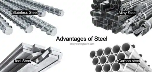
In general there are variety of materials used for various components of relief valve such as aluminum, stainless steel, brass, plastic, but the material used for spring which is provided inside the relief valve are generally made up of stainless steel or carbon steel. Most economical material is brass while aluminum is used where consideration is given to the weight. Plastic is used when cost is being reduced and stainless steel is used when fluid used is corrosive in nature.
The selection of material for relief valve is done on the basis of fluid property (if the nature of fluid is hazardous then the material should be such that it can discharge it safely) as well as temperature on which valve is being operated. One of the major disadvantage of the relief valve is it is subjected to the premature opening of valve when the device is subjected to bouncing movement.
Components of a Relief Valve
1. Valve Element
Valve element include spring loaded poppet which have elastomer seal. Upstream pressure and the spring apply opposite forces on valve. When the upstream pressure exerts force more than the force applied by spring then from the valve seat poppet moves away and results in passing of fluid from the outer port. When the force applied by the upstream pressure is less than the set pressure then valve closes.
2. Piston
Pistons are generally used when there is high relief pressure are required. Whenever there is application of low pressure and requirement of high accuracy diaphragm style is used over piston. In diaphragm there is a element of disc shaped used for sensing the pressure change. The problem of friction is eliminated in case of diaphragm.
3. Spring
Spring directly exert pressure force on sensor element which close the valve.
Types of Relief Valves
1. Direct Type of Relief Valve: ( Types of Relief Valve )
The direct type relief valve has two ports, the first port is pump port at which the pressurised fluid is being applied and the second port is the tank port. This type of relief valves are kept inside a hydraulic circuit when the pressurised fluid which is coming inside the valve, if that pressurised fluid is having pressure more than the specified pressure or the predetermined pressure then the valve will get actuated and it will bypass the excessive pressurised fluid to the tank, to have this arrangement we have the body of the valve. The body of valve is having a passage or it is also called as control chamber.
Inside the control chamber a poppet is used, the poppet is the spring loaded poppet and it can adjust the spring loading by using a screw. When the applied pressure is more than the set pressure by the spring the poppet will move in the upward direction and the excessive pressurized fluid will pass through the passage provided and it will bypass to the tank.
During the operation there may be leakage of the fluid inside the upper portion of the body of pressure relief valve and to drain that leaked hydraulic fluid inside the body a small passage provided. This will protect the failure of the valve due to the leakage problem.
2. Unloading Relief Valve: ( Types of Relief Valve )
The unloading valve operation is very much similar to the direct control valve. The unloading valve has a control chamber, a adjustable spring. The adjustable spring is pushing the spool down. The unloading valve has two ports that is a pump port and the tank port and there is also a remote pilot pressure signal port.
How it Work?
In normal condition this valve is a closed valve and this is allowing the system to run at a constant pressure and at minimum load application but when the pressure is increased and the pressure is about the critical value then the valve will get operated and the valve will get pushed in upward direction and the excessive pressure of the hydraulic fluid will be released by passing the fluid to the tank itself. In certain cases if there is signal arrangements, sensor arrangements and the microprocessor arrangements and this sensor and microprocessor arrangements is continuously monitoring the fluid pressure inside the system.
Based upon the signal received by the sensors and decision taken by the microprocessor we can actuate a pressure signal to the pilot arrangement. The pilot arrangement is nothing but an externally applied hydraulic fluid, with the separate system is there and that separate system is applying pressurized fluid at this location.
Through this passage by using the solenoid walls which are operated by the microprocessor, spool is pushed in upward direction. As the spool is pushed in upward direction the tank port will get open to the pump port and the excessive pressure which is build up at the pump that will be released by passing the excessive pressurized fluid through the tank. So in this way continuous monitoring of the fluid flow inside the system is done and automated fluid flow monitoring system is achieved by using the sensors and microprocessor arrangement.
3. Pressure Reducing Valve: ( Types of Relief Valve )
The purpose of this valve is to limit the outlet pressure inside the system. By controlling the outlet pressure, safeguard of hydraulic system is done.
Parts of Pressure Reducing Valve
The pressure reducing valve has a body which has a chamber and the chamber is housing the spool, the spool is being maintained by the spring and the spring is being controlled by a pressure adjustment screw. The stiffness or the pressure on the spring is controlled by the pressure adjustment screw. The wall has two ports that is a pump port and the outlet port.
Working of Pressure Reducing Valve
When the outlet pressure is more due to certain reason for example this kind of walls were used for holding purpose, the pressurized fluid is applied to hold or to clamp a device. The excessive pressure which is being applied inside the system mainly lead to the failure of the work part or it may lead to failure of the system itself.
So when the pressure at the outlet is more the back pressure which is created is applied at the bottom side of the spool and that back pressure will push the spool in upward direction against the spring, and as the spool is moved in upward direction the pressure at the outlet port will get relieved, pressure at the outlet port get reduced and in this way damage can be saved and wall can be protected from damage.
Whatever be the fluid, it will be leaked in the gap between the spool and wall body that will be drained to the wall port or drain port. A pressure reducing valve is allowing free flow of the pressurized fluid from the pump to the controlled pressure outlet until a signal from outlet port which is asking to throttle the passage through the valve which means that there is continuous flow is allowed but in case there is increase in pressure at the outlet a control signal is needed that signal is making the throttling of the fluid that is reducing the pressure of fluid inside the system and that is just possible by providing simple control signal line as given in the diagram.
4. Conventional Spring Loaded: ( Types of Relief Valve )
In this type of relief valve the spring, guide and bonnet are generally exposed to the fluid flowing. The relief system backpressure lowers the set pressure when bonnet vented to atmosphere and the relief system backpressure increases set pressure when bonnet are vented internally to outlet. They are generally used for noncorrosive services and the place where backpressure is less than 10 percent of the pressure which was set.
5. Balanced Spring Loaded: ( Types of Relief Valve )
These valves are used for protecting the spring; guide and bonnet from the fluid which is released in valve and it reduce the effect of backpressure. The disk area which is exposed to the backpressure is equal to the area of disk vented to the atmosphere. The advantage of using this type of valve is that they can be used for corrosive or dirty services in which there are variable backpressures.
6. Pilot Operated Relief Valve: ( Types of Relief Valve )
This type of are controlled and combined with an auxiliary pressure pilot. With the process pressure through orifice resistance force on the piston of main valve was assisted. As the process pressure around the set point increases the net seating force also increases.
Image Source :- sciencedirect, accutestsystems