Plasma Cutting: Definition, History, Process, Applications, Advantages & Disadvantages
Plasma Cutting Introduction:
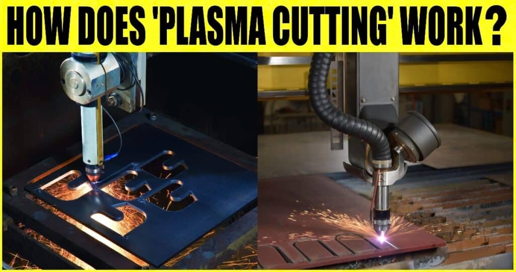
Plasma Cutting: Definition, History, Process, Applications, Advantages & Disadvantages: – A stream of ionised gas heated to temperatures above 20,000°C is used in plasma cutting or plasma arc cutting to melt and expel material from the cut. An electrode (cathode) and the workpiece come into contact with electricity during the process (anode). The small, high-temperature, high-velocity plasma jet forms when the arc is constrained by the electrode’s recess in a water- or air-cooled gas nozzle. The process occurs, and the gas returns to its natural condition when the plasma jet strikes the workpiece, producing great heat. The metal is melted by this heat and ejected from the cut by the gas flow.
Typically, argon, argon/hydrogen, or nitrogen are used as plasma gases. Air can be used in place of these inert gases. However, a specific electrode made of hafnium or zirconium is required. For cutting carbon-manganese and stainless steel up to 20 mm thick, compressed air makes this type of plasma process extremely competitive with the oxy-fuel technique. For precise cutting in reactive alloys, inert gases are preferred.
Numerous electrically conductive alloys, such as plain carbon and stainless steel, aluminium alloys, nickel alloys, and titanium, can be cut using a plasma arc. The technique was initially created to cut materials that the oxy-fuel process could not sufficiently cut. The plasma torch is often moved while the component or sheet being cut stays stationary. Furthermore, it is typical to attach multiple plasma torches to a cutting table due to the inexpensive cost of the plasma torch compared to the manipulation equipment. Utilising specialised equipment, plasma cutting can also be done underwater. A significant advancement in plasma arc technology is high tolerance plasma arc cutting. It can be a less expensive alternative to laser cutting and provides superior precision for less than 12 mm thick materials.
History of Plasma Cutting:
In the 1960s, plasma welding gave rise to plasma cutting, which later became a very productive method for cutting plates and sheet metal. Plasma cutting produces precise cuts and does not produce metal chips like conventional “metal vs metal” cutting. The first plasma cutters were huge, expensive, and slow. They were, therefore, mostly employed in mass production mode to repeat cutting patterns. From the late 1980s through the early 1990s, the plasma cutter utilised CNC (Computer Numerical Control) technology, just as other machine tools.
Plasma cutters now have more freedom to cut a variety of forms based on varied instructions encoded into the numerical control of the machine, thanks to CNC technology. However, CNC plasma cutting machines were often only capable of using two axes of motion to cut designs and pieces from flat steel sheets.
The Process of Plasma Cutting
The plasma cutting technique uses a sustained stream of heated plasma to cut through electrically conducting materials. Steel, stainless steel, aluminum, brass, copper, and other conductive metals are common materials cut with a plasma torch.
Manufacturing, vehicle repair and restoration, industrial building, salvage, and scrapping use plasma cutting extensively. Plasma cutting is commonly employed in large industrial CNC applications to small hobby firms where the materials are then used for welding due to the high speed and precision of the cuts at low cost. Cutting using plasma Plasma cutting is unique because it uses conductive gas, which may reach temperatures of 30,000°C.
Creating an electrical channel of superheated, electrically ionised gas, or plasma, from the plasma cutter itself through the workpiece to be cut, then establishing a completed circuit back to the plasma cutter through a ground terminal, is the fundamental process in plasma cutting and welding. This is done by blowing a compressed gas oxygen, air, inert gas, or another gas, depending on the material to be cut at high velocity via a focussed nozzle and into the workpiece.
An arc develops in the gas between the workpiece and an electrode close to the gas nozzle. An electrically conductive plasma channel is produced when this electric arc ionises a portion of the gas. This plasma generates enough heat as the cutting torch’s current passes through it to melt through the workpiece. In addition, a significant portion of the compressed gas and high-speed plasma blow the hot, molten metal away, separating the workpiece.
For both thin and thick materials, plasma cutting is a reliable method. Steel sheets up to 38 mm thick can often be cut using hand torches, but 150 mm thick steel can be cut with powerful computer-controlled torches. To cut and weld sheets in curved or inclined shapes, plasma cutters create a highly hot, localised “cone” for the cutting process.
Step 1. Pilot Arc Initiation
A start instruction causes the power supply to produce up to 400VDC of open-circuit voltage (also known as no-load voltage) to start the operation. This also starts the flow of compressed plasma gas into the plasma torch assembly, which includes an electrode and a plasma nozzle.
The power source also applies a negative voltage to the electrode, establishing it as the cathode of the pilot arc circuit, and closes the normally-open nozzle circuit contacts, temporarily applying a positive voltage to the nozzle, which then acts as the anode of the pilot arc circuit, as shown in the Pilot Arc Initiation diagram in above. A high-frequency spark is then produced by the arc starting console (ACS), establishing a high-frequency, high-voltage potential between the electrode and nozzle.
A low-resistance current route between the electrode and nozzle is created when the plasma gas is ionised by the spark, making it electrically conductive. As energy flows and discharges between the two components along this current channel, a first, low-energy arc also known as the pilot arc is created.
Step 2. Main Arc Generation
When the pilot arc is started, the plasma gas flows through the nozzle aperture and onto the grounded, electrically conductive workpiece, partially ionising the space in between and creating a new, low-resistance current route. The pilot arc finally makes contact with and transfers to the workpiece as the gas flow pushes it deeper through the hole. This arc transfer creates the main arc or the plasma arc that performs the cutting operation, as shown in the Main Arc Generation schematic above.
It also includes the workpiece and electrode in the newly formed main arc circuit. To improve the ideal cutting amperage, the arc transfer also causes the power supply to reopen the normally closed nozzle connections, detaching the nozzle from the main arc and pilot arc circuits.
Step 3. Localised Heating and Melting
As the ionised gas and main arc pass through the nozzle aperture, the nozzle restricts them, increasing the energy density and velocity of the plasma. The plasma produced by plasma cutting equipment reaches temperatures of up to 20,000°C and travels up to three times the speed of sound towards the workpiece. The cutting process uses this heat and kinetic energy. Melt-and-blow cutting, used in the plasma arc cutting process, heats, melts and vaporises a specific workpiece area.
The material of the workpiece absorbs the thermal energy of the arc and plasma gas as the plasma impacts its surface, increasing internal energy and generating heat. This weakens the material and enables it to be removed to create the desired cuts.
Step 4. Material Ejection
The kinetic energy of the plasma gas propels the workpiece’s weaker material out of the kerf, the width of material eliminated and the cut product. Too low or too high plasma flow levels result in less precise cuts and component failure. The ideal flow of the plasma gas is dictated by the current and the nozzle.
Step 5. Arc Movement
The plasma arc is manually or automatically pushed across the workpiece’s surface to generate the entire cut after localised heating, melting, and vaporising have begun. With handheld plasma arc cutting devices, the process is manually started, and the cuts are made by moving the torch across the surface. The machine is con d to move the torch head at the recommended speed for automated plasma arc cutting systems to achieve accurate and exact cuts.
Plasma Cutting Applications:
For thin metal processing, factory upkeep, agricultural upkeep, welding repair shops, metal service shops (scrap, welding, and dismantling), construction work (like building and bridges), commercial shipbuilding, trailer production, car repair, and artistic endeavours, workshops typically use manual plasma cutters (manufacturing and welding).
Cutting tables are frequently used with mechanical plasma cutters, typically much larger than manual ones. Punching, laser, or robot cutting systems can all be connected with mechanised plasma cutters. The employed table and portal determine the size of a mechanised plasma cutter. Since these systems are difficult to manoeuvre before installation, all of their parts, as well as the system’s layout, should be taken into account.
Advantages of Plasma Cutting
- Cutting of all materials that conduct electricity
- Cutting of medium- and large-thickness high-alloy steel and aluminium materials
- Outstanding performance in mild steel thicknesses of small and medium.
- Cutting of structural high-strength steel with less heat input
- Rapid cutting rates (up to 10 times higher than with oxyfuel)
- The preparation of premium blanks for medium- and thick-gauge sheet metal
- Automation is assured with plasma cutting.
- Low heat exposure and low noise levels are possible when plasma cutting under water.
Disadvantages of Plasma Cutting
- Limitation on the usage of up to 120 mm for underwater cutting and 160 mm (180 mm) for dry cutting
- A somewhat larger kerf
- Comparatively high-power usage
- Lasers provide even better-cutting quality.
- More expensive than cutting methods using oxyacetylene
- Dry cutting may cause noise growth
Image Source: – thefabricator, fabtechexpo
