Hand Pump: Types, Components, Mechanism & Working Principle

What is Hand Pump?
Water Hand Pump: Types, Components, Mechanism & Working Principle :- Talking in the layman’s language a hand pump is referred to as a mechanical device or a pump which uses the manual man power in order to lift water from the well. These are one of the most basic types of pumps which have been in use since years and years and are still in use which can be commonly seen in rural areas of the country.
Hand Pumps are considered as the boon to mankind as they are used to provide a cost-efficient water pumping solution to most of the remote areas. There are various types of water hand pumps which are used and it is also found that most of them have a similarity in design and working. The most important component of a hand pump is its handle, pump rod, piston, piston valve, suction lift and water outlet.
There are numerous configurations in a hand pump which generally varies with depth at which the water is available which needs to be pumped to the surface.
Positive Displacement Hand Pumps
The most common type of pumps which are in use are the positive displacement hand pumps. These pumps are armed with a reciprocating plunger or piston which are installed with a non-return values and sliders within a cylindrical tube. This piston is kept connected to the pump handle which once used results in upward and downward movements of any piston. As soon as the piston comes up it is found creating a vacuum which results in the water that gets sucked inside the cylinder and also gets drained via the outlet pipe.
Types of Hand Pump
There are various types of hand pumps which are commonly known to mankind. Some of them are as follows:
1. Direct Action Hand Pump: ( Types of Hand Pump )

Direct pumps refers to as that types of pump which consists of an operating rod and works on the principle of positive displacement. The best part of these type of pumps is that they are easy to install and have a low maintenance cost. The only limitation which it has is that it can only be lifted up to 15 meters.
2. Deep Well Hand Pump: ( Types of Hand Pump )

Deep well hand pumps are used at places wherever the water has to be lifted from a deep source. These pumps are used over 15 meters of depth. Deep well hand pumps include the weight of the water which is to be lifted and is too high, to aid a human in operating this pump. In such cases some mechanical additions like a lever or flywheel are used to make the work easier. Here are some more details about the installation and maintenance of deep good hand pumps:
- It is quite complicated and expensive in comparison to other hand pumps. These are the kinds of pumps which are found to be stronger in owing the nature of the work involved.
- A deep well hand pump is found having no limitation when it comes to the depth at which it can operate.
- Practically it is limited by the strength of human. The deep well hand pumps in general are found having an operational depth of 80 meters.
3. Diaphragm Pump: ( Types of Hand Pump )
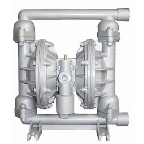
These are the types of pumps which have positive displacement pump in them. Comparing it in terms of weight, it is found to be lighter as they are found having no pulling rods in them. Other than this there is a usage of rubber and plastic tubing which makes it corrosion-free to a certain limit.

4. Progressive Cavity Pump: ( Types of Hand Pump )

Progressive cavity pump is also a type of positive displacement pump. This pump is found having more efficiency even after a compact design. The pumps includes a helical rotor which is inserted inside a double helical stator. As soon as the rotor moves, the cavity is filled with water and is eventually pumped out.

Design being compact, its typical gear mechanism system makes it nearly impossible for a local technician to repair or maintain it. As the pump is found having a typical mechanism, this is what increases it cost also. Considering a simple example of progressive cavity pump a rope and washer pump could be some amongst them.
Components of Piston in Hand Pumps
The parts of a hand water pump including its components are made by various manufacturers. Whereas its design, material and piston-type pumps can differ. The number and function of the different parts remains nearly constant. The difference might be seen in the case of construction and maintenance as some of the hand pumps are quite easier to repair and maintain than others.
Here are some of the parts which can be found in one or another form in mostly all the piston-type hand pumps. Scroll down to learn more:
1. Riser Main Pipe
The riser main pipe is the vertical pipe which is responsible for pumping water from the water table to the pump head. It’s usually range is around 1 ½ to 2 ½ inches in diameter which can be a steel pipe section threaded together or a PVC pipe section usually sealed together in order to avoid leakage.
In case of a closed-top pump cylinder, the main riser is found having a smaller diameter as compared to the pump cylinder whereas in an open-top pump cylinder, the main riser is found having the same diameter as that of a pump cylinder.
2. Pump Rod
A pump rod is referred to as a solid steel rod which is about a half inch in diameter and is used to connect the assembly of the piston in the pump cylinder to the pump handle. The operation of the pump handle is responsible for moving the pump rod and the piston assembly upwards or downwards.
3. Upper Cap
The upper cap is used on the closed-top pump cylinder in order to seal the interior of the pump cylinder and to also define the limit of motion of the piston assembly. Here it should be noted that the open-top pump cylinders are found having no upper cap.
4. Cylinder Barrel
The cylinder barrel constitutes of a main body of the pump cylinder. The piston seals presses up against the inside wall of the cylinder barrel in order to form a seal which is responsible for creating a pressure difference between the upper and the lower part of the cylinder as the pump continues to operate.
5. Piston Assembly
A piston assembly is commonly named as plunger and is also termed as the business end of a piston pump. It is found having a housing, of the material brass, plastic, or stainless steel which carries the piston valve and the piston seals. This is further connected to the pump rod. This is the main action of the piston assembly that lifts up the water out from the well.
6. Piston Valve
Piston valve is held within the piston assembly which is a one way valve and allows water to flow in the upward direction into the upper cylinder, whereas closed on the up-stroke pushes water up to the riser main.
7. Piston Seals
Seals which are made of leather and are soaked in oil or made of rubber those are used to seal the piston assembly against the inner walls of the pump cylinder. The piston seals are used to define the boundary with the upper cylinder and the lower cylinder. Whenever any part of the piston assembly is in motion, there is an amount of pressure difference across the piston seals. This pressure difference is the one which allows water to move inside the bottom of the cylinder and out from the top into the riser main.
8. Foot Valve
The foot valve is located inside the lower cap which is another one-way valve often identical to the piston valve. The foot valve is found allowing the water to flow upwards into the lower cylinder on the up-stroke and to hold it there during the down-stroke.
9. Lower Cap
The lower cap seals the interior of the pump cylinder at the bottom. It houses the foot valve and defines the downward limit of travel of the piston assembly.
10. Tail Pipe
A tail pipe is referred to as an extension of the pump cylinder which is sometimes added whenever the level of water in the aquifer is variable or drops below the pump cylinder. This effectively extends the operational depth of the pump by adding a short length of the riser main material down into the lower water level.
Operations Of Hand Pumps
Lifting
Considering the first operation lifting, lifting out water from a well always includes overcoming the weight of the water in order to raise the water from some depth to the surface where it can be used, stored or transported. There are various methods which have been formed in order to accomplish it, from a simple to complex form.
For instance, the hand-dug wells are found doing this consistently with a simple rope and bucket where water is physically lifted out of the well. This is considered one of the best example of direct lift. Some other sophisticated methods of direct lift are provided by propeller pumps, centrifugal pumps, air lift pumps and siphons. The hand water pumps are most commonly classified as displacement pumps or positive displacement pumps.
It is interesting to know that the majority of pumps are used in developing nations from the displacement pumps as the water cannot be compressed rather it can be pushed or displaced. The most popularly known displacement pumps are also termed as piston pumps as they utilize a piston which is sealed within a cylinder in order to displace water upwards out from the well.
It is interesting to know that the piston pumps falls into two categories first is suction pump and the other one is the lift pump. However the other pumps which take advantage of this principle inculcate the progressive cavity pumps and diaphragm pumps.
Suction Pump
A suction pump is referred to as that type of hand water pump which was frequently used in the older days for pumping water to meet out the day to day needs. In a suction pump, the pump cylinder and the pump valves are placed above the ground in the pump head. The repeated strokes of the pump gradually handles the riser main into the cylinder and exits it from the spout.
Due to its mechanical limitations, the operational depth of a suction pump is known to be limited up to 8 meters. The lift pumps are popularly found in developing the world due to the depth by which the water must be drawn from exceeding the limits of a suction pump.
Working
Suction pumps are known to be easier to work as compared to the lift pumps as the pump cylinder and its parts are above ground and are found to be accessible easily. Whereas, most of the water-yielding aquifers are quite too deep for the suction pumps therefore, the lift pumps are more popular. However, piston pumps are found having their pump cylinder below the ground and the level of the water table.
Rather than sucking the water out from the well it is lifted in columns of water upwards with the help of the riser.
Each and every stroke of the pump is responsible for handling the displacement of the piston and more water up the riser till it flows out from the spout. The theory however says that there is no limit to the depth from which a piston pump can remove water whereas practically, the limit is determined by the amount of power a human being exerts on the pump handle and the type of construction and materials of the pump cylinder, pump rod, piston valves, and piston seals.
Here, the pump cylinder is below the water table for which a long pump rod is required to reach down to the pump cylinder which connects to the pump handle. This is responsible for complicating the maintenance process since the pump rod, the riser main and the pump cylinder has to be removed from the well, which can even be hundreds of feet in depth.