Coil Winding Machine: Introduction, Types, Working Principle & Process [Complete Guide]
Introduction of Coil Winding Machine
Coil Winding Machine: Introduction, Types, Working Principle & Process :- Referring to electrical engineering, a coil winding is referred to as the manufacturing of electromagnetic coils. These coils are used as components of circuits which provides the magnetic field of motors, transformers and generators and is also used in the manufacturing of loudspeakers as well as microphones.
The shape and dimensions of a winding are designed in order to fulfil any particular purpose. There are parameters such as inductance, Q factor, insulation strength and strength of the desired magnetic field which greatly influences the design of the coil windings. Coil windings are found to be structured into various groups regarding the type and geometry of the wound coil. The mass production of electromagnetic coils relies on the automated machinery only.
Types of Coil Winding Machine
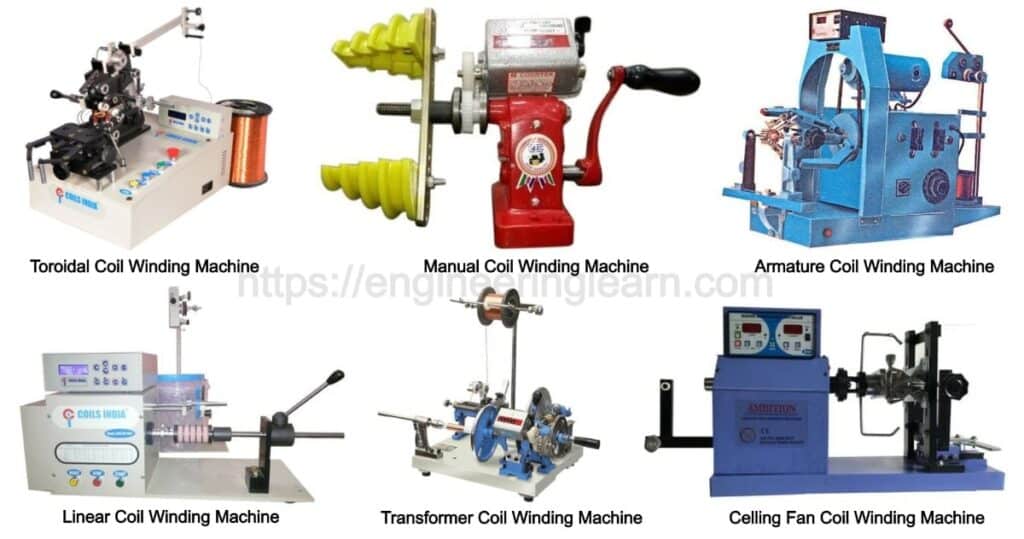
Based on the common mechanism of working, coil winding machines are commonly known to be of different types, which are as follows. After having a detailed study, you will definitely be able to select the most appropriate winding machine to fulfil your purpose according to your site condition.
1. Manual Motor Coil Winding Machine
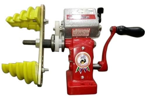
These are referred to as the types of winders which are found to be highly useful for small-scale industries or workshops wherein the winding requirement is not too frequent. Manual coil winding machines are found to be operated with hands and are also referred to as giving precise results in terms of coil loops.
2. CNC Linear/ Toroidal Coil Winding Machine
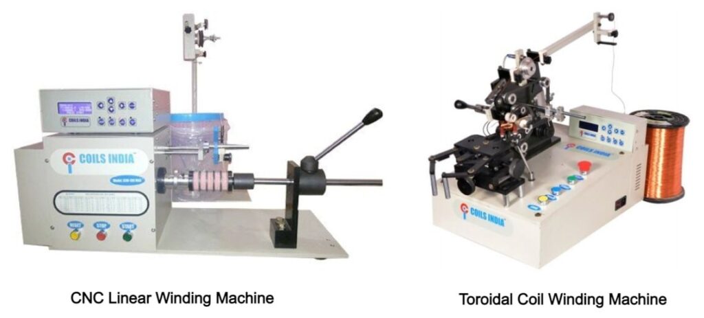
CNC linear / toroidal winding machines are mostly used at those places wherein any one is looking for an automated winding solutions for customized one-off coils or small quantity batches of coils, then you must opt for CNC winding machines which can be the best for your purpose.
3. Armature Coil Winding Machine
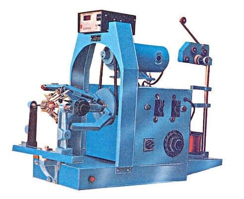
These are the type of winding machines which are well suited for standard as well as customized armature field coil winding requirements. These types of machines are ingeniously designed device with hook commutators. There are various winders which come with an auto wire cutting and hooking option as well.
4. Transformer Coil Winding Machine
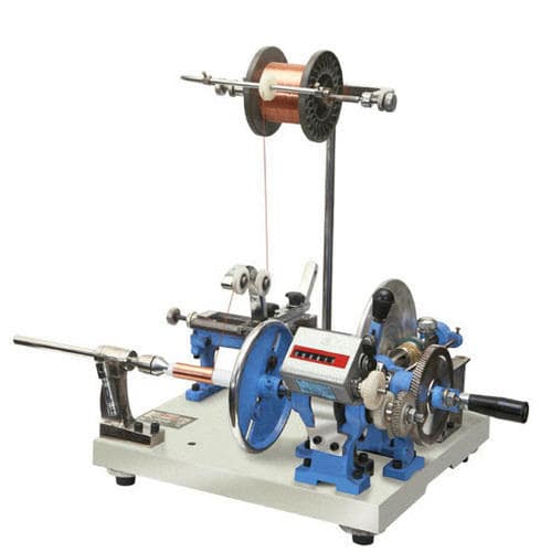
Transformer coil winding machines are known for their flexibility, robust built and durability as these winding machines are found to be capable of winding the coils of various sizes and shapes for the transformers. These machines are commonly known as these can also approach those places which are not accessible due to any site condition. This is how the flexibility of this machine works in the real world.
5. Ceiling Fan Coil Winding Machine
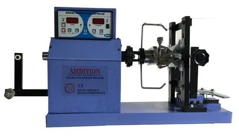
Ceiling fans are mostly very commonly known electric instruments which are widely used all over the world. The starter which is present inside it, gets burned on an excessive usage or due to any other technical issue. So in order to rewind it, and repair it, there is a ceiling fan winding machine which is mostly used for winding the coil in this case.
There are various types of ceiling fan winding machines which are below mentioned:
A) Hand Ceiling Fan Winding Machine
These are the types of fan winding machines in which the rewinding process is done manually or by hand.
B) Semi- Automatic Ceiling Fan Winding Machine
These are referred to as the winding method in which there is a slight involvement of machinery in the rewinding process.
C) Fully Automatic Ceiling Fan Winding Machine
These are referred to as the winding method in which the complete process of winding is done using the machine. This is the most convenient type and is mostly preferred in the industries.
Importance of Coil Winding Machine
Transformers are referred to as those which are found requiring different coils that have varying requirements of winding. There are various factors which have to be considered while coil winding for transformers like:
- Number of loops
- Wire cutting
- Wire hooking
- De-spooling
- Wire tension
- Traversing
With the help of a proper coil winding machine, these are the factors which can be taken care of with accuracy. Automated winding machines are designed specifically in order to avoid the unwanted breakage of the wire or any other glitches. May it be medium or heavy duty coil winding requirement, the winders are capable of giving error-free and consistent results. The transformer industry gives the benefits from the highly controlled working mechanism of coil winders.
Working Principle of Coil Winding Machine
Coil winding machine is quite popularly known these days, but on the same time it is mandatory to know on what principle it works. So, here is a proper description of the principles of coil winding machine which will help you in learning things in a better way.
Introduction
Efficient coils are found to minimize the materials and volume which is required for a given purpose. The ratio of the area of electrical conductors, to the provided winding space is referred to as the fill factor. Since the round wires are found to have some gap always along with the wires which have some space that is required for the insulation within turns and layers, the fill factor is mostly smaller than one. In order to achieve higher fill factors, a rectangular or flat wire can be selected.
Dense packing of wires is done which is responsible for reducing the air space and is said to have a high fill factor. This is the reason which increases the efficiency of the electrical device and an improved heat conductivity of the winding. For best packing of round wires on a multi-layer winding, the wires in the upper layer are found to be in the grooves of the lower layer for at least 300 degrees of the coil circumference. The wires which occupy a dense package which is referred to as orthocyclic winding. The opposite of this would be a random wire structure within the winding space, which is referred to as wild winding.
Wild Winding
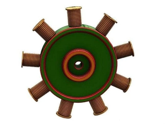
Wild winding is referred to as the random wire placement which leads to a wider distribution, resulting wire length on the coil body and consequently a wider range of electric coil resistances. Despite its various disadvantages, it is common in mass production. It is characterized by low demands for machinery and operator which can be wounded with very high speed. Wild windings are mostly applied in the contactor- and relay coils, small transformers, Ignition coils, small electrical motors and generally those devices which are found with relatively small wire gauges up to 0.05 mm.
Helical Winding
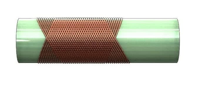
Helical windings is the method in which the wires are placed helically in every layer. Owing to the direction of movement from layer to layer changing between right to left, the wires are found to cross and locate themselves within a specific gap of the layer underneath. A wire which guides of the lower layer is not found to be existent. In case the number of layers exceeds a certain limit the structure cannot be maintained and a wild winding is also found to be created.
Orthocyclic Winding
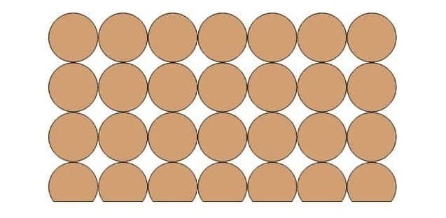
Orthocyclic winding is referred to as a type of winding structure which creates an optimal fill factor for the round wires. The windings of the upper layer needs to be placed within the grooves which is provided by the lower layer.
The best use is found once the winding is found to be parallel to the coil flange for most of its circumference. As soon as the winding has been placed around the coil body it will meet the previous positioned wire which needs to make a step with the size of the wire gauge. This movement is referred to as a winding step. The winding step is found to occupy an area of up to 60 degree of the coil circumference for round coil which takes one side of rectangular coil. The area of the winding step is found to depend on the wire gauge and coil geometry.
Process of Winding
By now, the principle of coil winding must be clear, now one needs to know what all processes are including in the process of winding. So, below mentioned is the detailed explanation of the processes which are involved in the process of winding.
1. Linear Winding: ( Process of Winding )
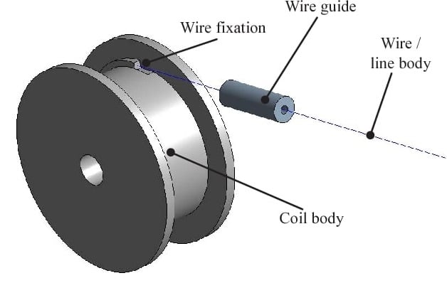
The linear winding method is referred to as that method in which a winding is produced by the help of winding the wire onto a rotating coil body, component, coil carrying, coil forming device. The wire is pulled out from a supply roll which contains around 400 kg of enamelled copper wire. The wire is fed through a guiding tube. Before starting the actual winding process, the wire is mounted in order to post or clamp the devices of the coil body or the winding device.
By using the linear laying movement of the wire guiding tube, the component which is to be wounded, is turned in a way that the wire is distributed throughout the winding space of the coil body. The rotary motion along with the laying movement is achieved by using the computer controlled motors. In reference to one rotation of the rotation axis and depending on the wire diameter, the traversing axis of the wire guides the tube which is moved accordingly.
This leads to the rotational speeds of up to 30,000 per min, especially while processing through the thin wires. Depending on the diameter of the winding, the speed of the wire can be up to 30 m/s which can be achieved during the winding process. The components which needs to be wounded are mounted on the winding devices. The winding devices are coupled with driven spindles that can generate the turning motion. Since bringing the wire into the winding area must be done as evenly as possible, the rotational axis along with the traversing axis operate synchronously during this whole winding process.
2. Flyer Winding: ( Process of Winding )
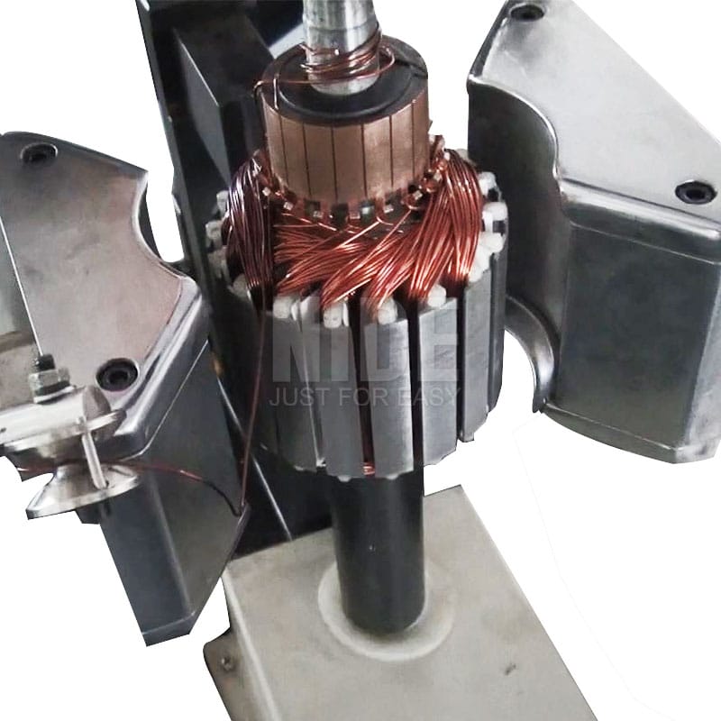
In the flyer winding method, a winding is produced by feeding the wire via a roll or through a nozzle that is attached to a flyer and is found to rotate at a certain distance from the coil. The wire is fed by the flyer shaft. For winding the component which needs to be wound, it needs to be fixed inside the winding area of the flyer. It is mandatory that the wire should be fixed outside of the flyer at any time of the winding procedure.
The fixation of the wire is made possible normally by the successive winding method which is often used at rotary indexing tables. At the circumference of the table there are the wire clips or wire deflections which enables a pull along and fixation of the wire. This will always allow a very quick component change, which gives that no separate depositing of the wire in a wire clip on the machine is required.
3. Needle Winding Technology: ( Process of Winding )
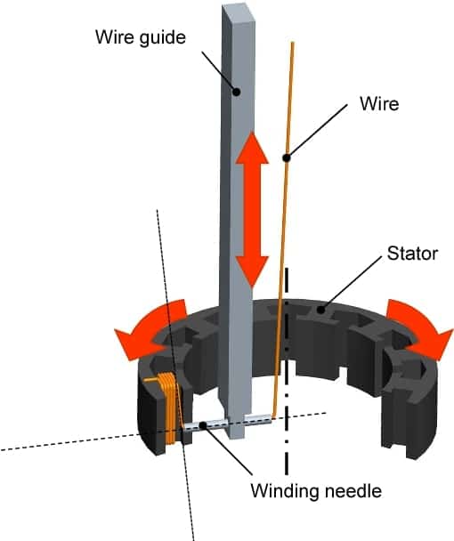
Needle winding technology is used to efficiently wind the pole shoes which are found lying close together in order to electronically commute multiple three-phase motors. These are found to be coated with an insulation which directly wounds with the needle winding method. A needle along with a nozzle which is placed at a right angle to the direction of movement travels in a lifting motion which passes the stator packs through the groove channel within the two neighbouring poles of the motor in order to drop the wire in the desired place. The stator is then found to turn at the reversal point on the winding head by one tooth pitch so that the previous process can run again in the reverse order.
With this winding technology a specific layer structure can be realized. The disadvantage is that there must be a clearance between two adjacent poles with a size of at least the nozzle diameter. The diameter of the nozzle is found to be about thrice the diameter of the winding wire. The space between two adjacent poles can therefore not be filled completely.
4. Toroidal Core Winding Technology: ( Process of Winding )
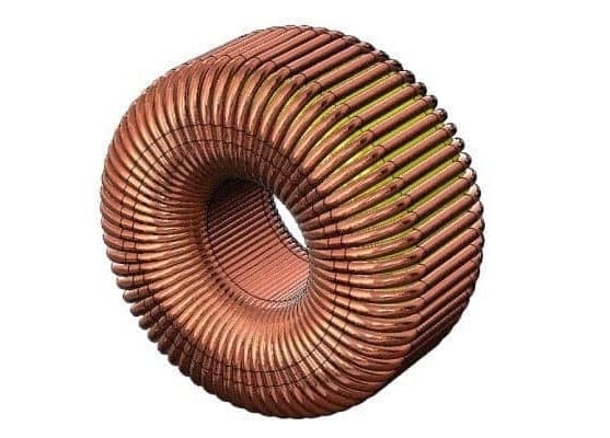
Before starting the winding process, the Toroidal / Magnetic core is found to be mounted into a holding fixture which that can initiate a slow rotary movement of the core along with mostly three rubberized points of contact.
A wire storage ring or orbital wheel is found to be arranged at an angle of 90° to the toroidal core which can now be opened at the circumference and introduced into the center of the toroidal core. After this, the wire is coiled around the wire storage ring so that it can be closed again. When the required amount is present on the wire accumulator, the end of the wire from the wire accumulator is fixed to the toroidal core which needs to be wounded.
By similar rotation of the toroidal core and the wire accumulator ring, a winding is found to develop which is distributed along the circumference of the toroidal core. After completion, the wire accumulator needs to be opened again in order to be able to remove the ready wound toroidal core. Since the start as well as the end wires are not often fixable to the toroidal core, the toroidal winding machines can only be partly automated.
Image Source :- iqsdirectory, semanticscholar
