Operation of Induction Motor
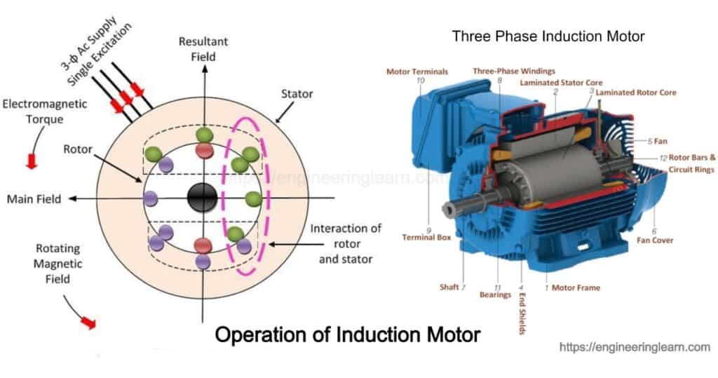
Operation of Induction Motor :- Three phase induction motors are most widely used electrical machine in industry. Three phase induction motor usually runs at constant speed with respect to no load to full load. Three phase induction machine provide some advantage that are simple in construction, low price range & easy in maintenance.
Construction of Induction Motor
Usually 3 phase motor consist of motor & stator. This stator carries a 3 phase windings while rotor carries winding from the short circuit called rotor winding. Only the stator winding from the 3 phase supply. Induction motor may be considered as transformer with a rotating secondary transformer or A.C machine in which electrical energy is converted into mechanical energy.
Types of Rotor Windings
1. Spiral Cage Types
It consist of laminated cylindrical core having parallel axis on to the outer periphery. 1 copper or aluminum bar is placed on the each slots. All of these bars are joined at the each end of the by metal ring called end rings. This forms a permanent short circuit winding which is indestructible. The entire base & end rings resemble a spiral cage.
2. Wound Types
This consist of laminated cylindrical core & 3 phase supply winding similar to the one on the stator. The rotor wounding is uniformly distributed in slots & connection with the mode of star connection. The open ends of rotor winding are brought out & joined to the three insulated slip rings mounted on the rotor shaft with one brush resting on the each slip rings.
Principle of Operation
- 3 phase stator winding is energized from the 3 phase supply, a rotating magnetic field is set up which rotates around the synchronous speed. (Ns = 120 f/ P)
- These rotating fields mutually pass through the air gap & cuts the stationary rotor due to relative speed b/w rotating flux & stationary rotor, thus E.M.F are induced in the rotor conductors. Since the rotor circuit is short circuited, current is flowing in the rotor conductors.
- These current carrying rotor conductor is place in the magnetic field produced by the stator. Mechanical forces act on to the conductor. The sum of the mechanical force acts upon the all rotor conduction produces a torque which tends to move the rotor direction in same direction of rotating field.
- In fact rotor is urged to follow the stator fields (rotor moves in the direction of stator field can be explained by Lenz law stated that direction of rotor current will be such that they tends to oppose the cause producing them, now the cause producing the rotor current is the relative speed b/w rotating field & stationary rotor conductor, hence to reduce this relative speed the rotor starts running in same direction as that of stator field & tries to catch it.
Slip:- slip is the difference between the synchronous speed Ns of the rotating stator field. The actual rotor speed N is called the slip. Slip is usually represented in percentage of synchronous speed.
