Coalescer: Definition, Types, Process, Uses, Design & Applications
Coalescer Introduction:
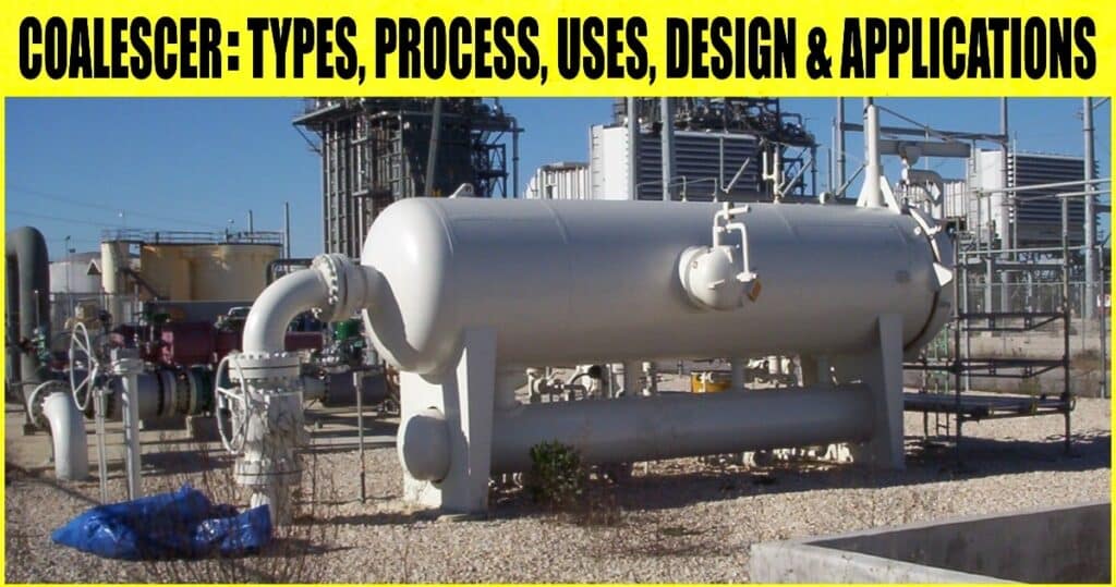
Coalescer: Definition, Types, Process, Uses, Design & Applications: – The liquid-liquid or liquid-gas separation from hydrocarbons is accomplished using a coalescer, a significant piece of industrial equipment for the oil and gas sector. The smaller hydrocarbon particles or droplets are merged into bigger ones and then separated by a coalescer using its baffles or electric current. This is sometimes referred to as a filter coalescer or a coalescing filter. This post will learn more about coalescing filters, including their kinds, operations, uses, and applications.
What is a Coalescer?
Industrial equipment called a coalescing filter or coalescer separates fluid mixtures into their parts. Sulfur, ethane, carbon dioxide (CO2), water vapor, methane, and other contaminants are present in industrial process fluids. These contaminants need to be taken out of the mixture to preserve the quality of the finished product. The coalescer uses the concept of Coalescence to separate these contaminants from the mixture.
For Coalescence, what does it Mean?
The word “coalescence” refers to a grouping of Coalescence. In Coalescence, fluid molecules group together to create a bigger unit, later divided into particulate components. The emulsification process is reversed in this procedure.
What Use does a Coalescer Serve?
A coalescer’s job is to use various techniques to separate mixes or emulsions into parts. They are capable of separating homogeneous and heterogeneous mixtures. You can use a coalescing filter separately or as a bigger separating system. Coalescers are a common piece of equipment for processing oil.
What is a Coalescer’s Process?
Multiple baffle walls or screens are distributed throughout the inside of a coalescer, coalescing filter, or filter coalescer. The filter is then used to apply the mixture that has to be separated. The separation device’s baffles screen out the components by encasing them in several compartments.
The screening mechanism operates by utilizing the molecular mass and density of separate components. For instance, the baffle walls inside the coalescer separate the heavier oil molecules in one direction to a drain point in the liquid-liquid coalescer used for water-oil separation. At the same time, water vapor molecules permeate past the filter element and clump together before being gravitationally drained from the system.
Similarly, when a gas stream containing water droplets is delivered into a coalescer, they diffuse through the filter element and leave the system through an outlet port as dehydrated gas. As they combine to create bigger water molecules, the heavier water molecules sink to the bottom of the tank for drainage.
Coalescer Types:
There are two main categories of coalescers: mechanical coalescers and electrostatic coalescers, depending on how they function.
1. Mechanical Coalescer
Mechanical coalescers function by using several filter components or barriers for separation, as was previously explained. The water droplets are directed to the barriers in a mechanical coalescer. On the other hand, when the oil passes through the baffle fibers, it becomes thinner. Water and oil separate from one another throughout the process. A classic illustration of a mechanical coalescer is the plate coalescer.
2. Electrostatic Coalescer
Electrostatic Coalescers may utilize both AC and DC current. A high voltage electrical field is applied to the water-in-oil emulsion. When an electric field is applied to a non-conductive liquid (oil in a water-oil combination) that contains a dispersed conductive liquid (water), the conductive particles join. There are three possible physical phenomena:
- After being polarised by the electric current, the droplets tend to align along electric force lines. The positive and negative poles of the droplets may be brought close together in such a circumstance. The droplets are drawn together and agglomerate due to the electrical attraction.
- The droplets may be drawn to an electrode by an induced charge. Small water droplets vibrate across a wider area in an AC field due to inertia, which encourages Coalescence. Droplets tend to gather on electrodes in a DC field, becoming bigger and bigger until they ultimately fall due to gravity.
- The electric field distorts and weakens the emulsifier layer surrounding the water droplets. The water droplets scattered in oil will lengthen along the force lines during the first half of the cycle when exposed to an alternating current field. When the droplets are loosened during the low-voltage phase, surface tension will draw them back toward the spherical form. A similar result is attained in the second half of the alternating cycle. As a result, when droplets meet, the weaker film is more readily broken, increasing the likelihood of Coalescence.
The electric field causes the droplets to travel quickly and randomly via any of the processes, which dramatically enhances the chance they will collide and merge. Typically, an AC current in the 50–60 Hz range is employed. In offshore oil and gas production facilities, electrostatic coalescers are widely used for separating water-fuel emulsions.
3. Plate Coalescer
There are many different configurations of plate coalescers. These are called corrugated plate interceptors, cross-flow separators, and parallel plate interceptors (PPI) (CPI). Gravity separation is essential to the operation of all plate coalescers because it enables the oil droplets to climb to the plate surface, where Coalescence and capture occur.
Several parallel plates placed 0.5–2 inches apart separate the flow, as seen in Fig. 1. The plates might be horizontally inclined at times. It encourages the Coalescence of oil droplets into films, which direct the oil to the top, where it is trapped in channels and keeps it from mixing with the water. The plates offer a surface for the solid particles to settle and the oil droplets to gather.
It is Advised to use Plate Separators When
- The water flows at a constant rate.
- There are no restrictions on size or weight.
- Sand concentration in the waste stream is less than 110 ppm, and solid pollutants are not substantial.
- Equipment and utilities are provided to clean the plate packs periodically.
- Influent oil concentrations are considerable, and for efficient second-stage treatment in a downstream unit, oil concentration must be decreased to 150 mg/l.
Plate Separators are not recommended when:
- Plate separators should not be used when
- The two main factors are size and weight.
- Influence droplets are smaller than 30 mm.
- Solids removal is the main goal, and sand particle sizes are fewer than 25 mm.
Coalescing filters are divided into several categories depending on the product they separate, including:
- Fuel coalescer,
- condensate fileter coalescer,
- natural gas coalescer,
- oil coalescer,
- gas coalescer, etc.
Coalescer Design
A coalescer can be set up either vertically or horizontally. Process requirements, safety, and economic considerations influence coalescer design. Before coalescer design, the following factors must be chosen:
- The lowest, average, and maximum gas and liquid flow rates.
- Operating and intended pressures and temperatures.
- Propensity to slug or surge the feed stream.
- fluids’ densities, viscosities, and compressibility
- the necessary level of separation
Coalescer Applications
- In the downstream oil and gas, petrochemical, and chemical industries, coalescers or coalescing filter separators are used for various applications for liquid-liquid or liquid-gas separation.
- Operations downstream: Coalescers in the oil and gas industry look for uses for the products to be refined. Coalescing filters are used in natural gas refineries to dehumidify natural gas and assure the quality and purity of the final product. Coalescers in a gas-oil system also cleanse the natural gas by removing condensate and several natural liquids.
- Again, by eliminating corrosive pollutants like sulfur, water vapor, etc., coalescers have the power to prevent corrosion of compressors, amine/glycol absorbers, turbines, and membrane filtering systems.
- Coalescing filters are put at the compressor inlet to collect lubricating oil from the compressor. Particulate debris, aerosols, dissolved hydrocarbon liquids, and slugs are frequently present in the fluids supplied into the compressor’s input. A coalescer is positioned upstream of the compressor to recover the oil and enhance compressor performance.
- Petrochemical Industries: Liquid-liquid coalescers can be used to phase separate water vapor, amine solutions, and sulfur from petrochemical feedstock before storage.
Content Source: – nigen, hollingsworth
Image Source: – kingtoolcompany
